EasyManua.ls Logo

ALLEN & HEATH GL4000 Service Manual

ALLEN & HEATH GL4000
98 pages
To Next Page IconTo Next Page
To Previous Page IconTo Previous Page
Page #38 background image
ALLEN & HEATH
GL4000 SYS-LINK OPTION
5
FITTING THE SYS-LINK HARNESS ASSEMBLY :
Refering to fig. 4, use a pair of long nosed pliers to fit the connectors onto GROUPS 1 - 8 and the LEFT
RIGHT and MONO circuit board assemblies in the following order:
GROUP 1 to GROUP 8, then LEFT, RIGHT and then finally the MONO circuit board assembly.
SYS-LINK WIRING HARNESS
SYS-LINK ribbon harnesses
removed for clarity.
SYS-LINK CIRCUIT
BOARD ASSEMBLY
8x GROUP CIRCUIT BOARD ASSEMBLY
LEFT CIRCUIT BOARD ASSEMBLY
MONO CIRCUIT BOARD ASSEMBLY
RIGHT CIRCUIT BOARD ASSEMBLY
fig. 4
SYS-LINK harness circuit board interconnections
1 2

Other manuals for ALLEN & HEATH GL4000

Question and Answer IconNeed help?

Do you have a question about the ALLEN & HEATH GL4000 and is the answer not in the manual?

ALLEN & HEATH GL4000 Specifications

General IconGeneral
TypeAnalog Mixing Console
Groups8
Faders100mm
Frequency Response20Hz - 20kHz
Channels40
Mic/Line Inputs40
EQ4-band with 2 sweepable mids
Direct OutputsYes
Phantom PowerYes
MeteringLED
Total Harmonic Distortion< 0.005% at 1kHz
Noise (EIN)-128dB
DimensionsVaries depending on frame size. e.g., 40 channel: 1367mm (W) x 724mm (D) x 223mm (H)

Summary

SECTION A

CIRCUIT BOARD REMOVAL AND ASSIGNMENT

Procedures for removing circuit boards and setting channel mute assignments.

SECTION B

GL4000 Expander Installation

Steps for fitting the GL4000 expander option to the console.

SYS-LINK EXPANDER OPTION

Instructions for installing the SYS-LINK option for console interconnection.

SECTION C

MONO / STEREO INPUT & TALKBACK

Schematic diagram of the mono/stereo input channels and talkback circuitry.

GROUP / AUX / MATRIX / LR / MONO / 2 TRACK

Block diagram showing signal flow for groups, aux sends, matrix, etc.

CIRCUIT DIAGRAMS

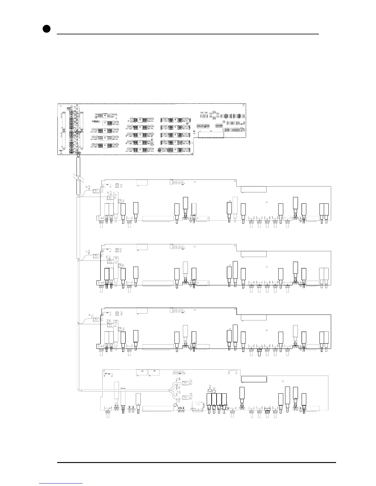
Detailed schematics for various PCBs like Mono Input, Stereo Input, Master, MPU, etc.

SECTION D

FUSE RATING & REPLACEMENT

Instructions for replacing the mains input fuse in the RPS11.

Related product manuals