Rockwell Automation Publication 750-IN011F-EN-P - June 2017 7
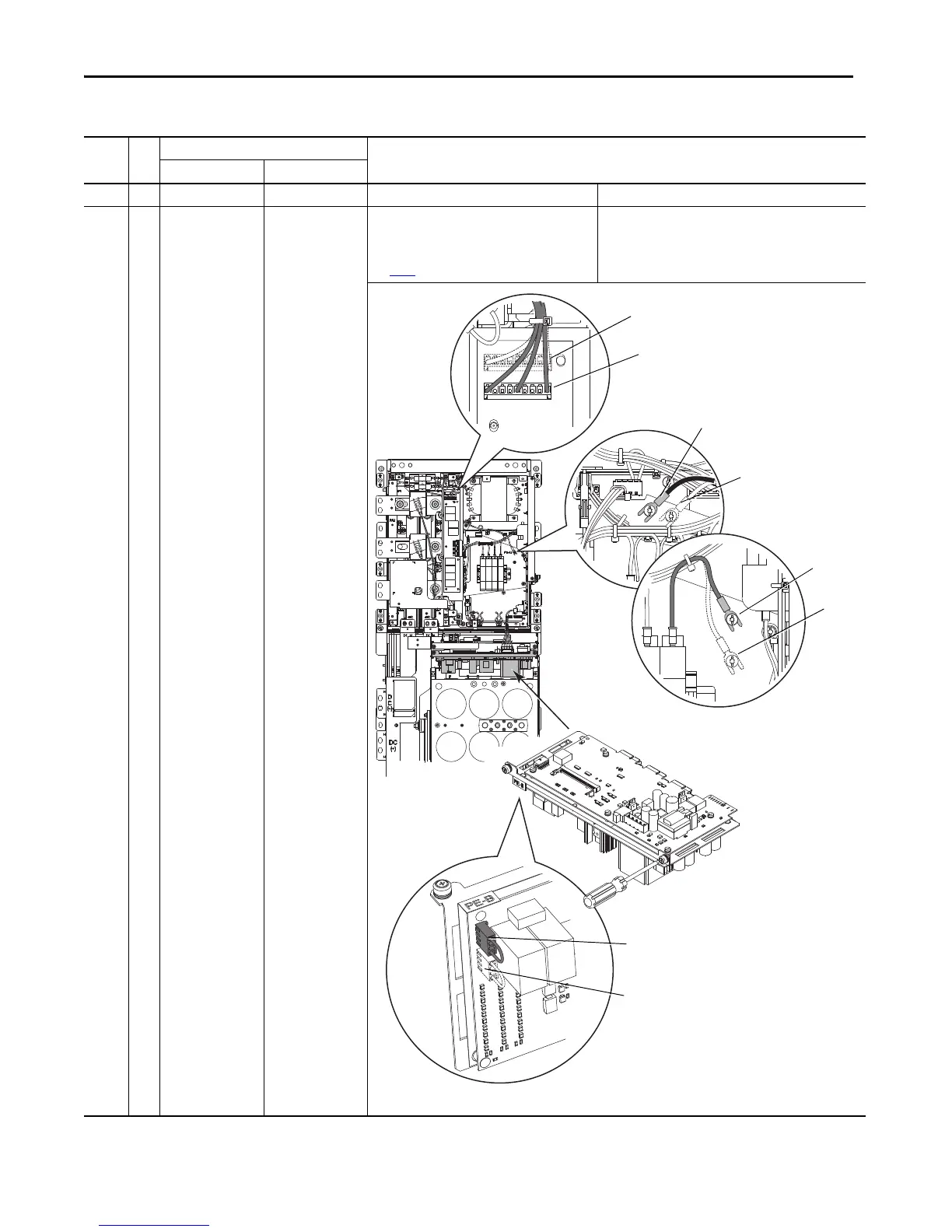
PowerFlex 750-Series Power Jumpers
8…10 C
D
E
F
PE-A1 & PE-A2
connected to ground.
PE-B jumper plug
insulated/disconnected
from ground.
PE-A1, PE-A2, and PE-B
connected to ground.
Solid Ground
Connect the MOV jumper wire (PE-A1), Input Filter Cap
jumper plug (PE-A2), and the CM Cap jumper plug (PE-B)
to ground.
See page 4
for recommended torque.
Non-Solid Ground
Insulate/disconnect the MOV jumper wire (PE-A1), Input Filter Cap
jumper plug (PE-A2), and the CM Cap jumper plug (PE-B) from
ground.
Jumper Locations and Settings (Continued)
Frame
Voltage
Code
Factory Default Jumper Settings
Power Source Type
Catalog Code ‘A’ Catalog Code ‘J’
Insulated (P2)
Connected (P3)
Insulated
Connected
Insulated (J4)
Connected (J3)
PE-A1 and GND positions on
early production drives.
1.86 N•m (16.0 lb•in)
Insulated
Connected
 Loading...

