Rockwell Automation Publication 22C-UM001J-EN-E - January 2017 29
Installation/Wiring Chapter 1
Maximum Control Wire Recommendations
Do not exceed control wiring length of 30 meters (100 feet). Control signal
cable length is highly dependent on electrical environment and installation
practices. To improve noise immunity, the I/O terminal block Common must
be connected to ground terminal/protective earth. If using the RS485 (DSI)
port, I/O Terminal 20 should also be connected to ground terminal/protective
earth.
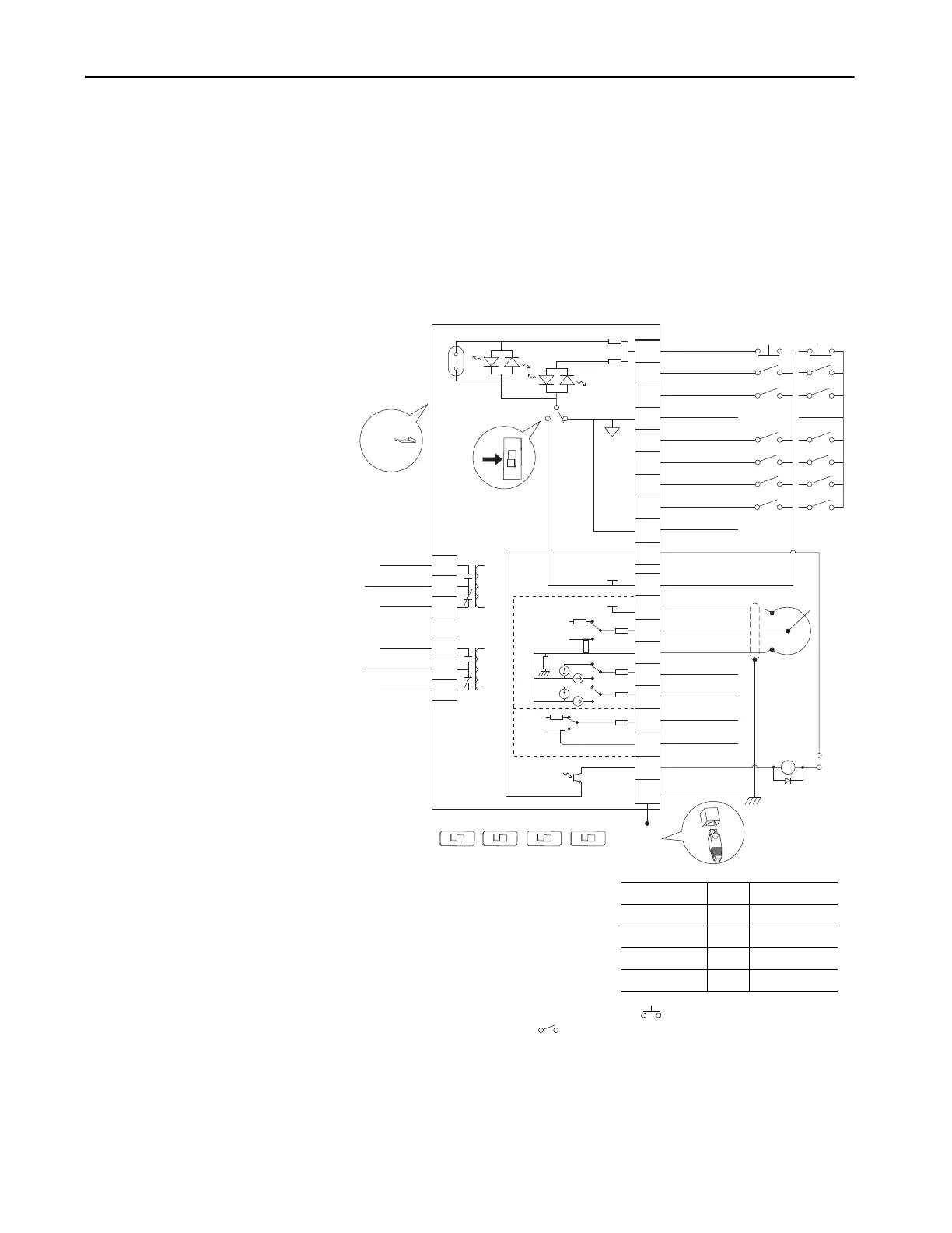
Figure 10 - Control Wiring Block Diagram
(1) Important: I/O Terminal 01 is always a coast to stop input
except when P036 [Start Source] is set to option 1 “3-Wire”
or 6 “2-W Lvl/Enbl”. In three wire control, I/O Terminal 01 is
controlled by P037 [Stop Mode]. All other stop sources are
controlled by P037 [Stop Mode].
Important: The drive is shipped with a jumper installed
between I/O Terminals 01 and 11. Remove this jumper
when using I/O Terminal 01 as a stop or enable input.
(2) Two wire control shown. For three wire control use a momentary input on I/O Terminal 02 to command a start. If reverse
is enabled by A166, use a maintained input for I/O Terminal 03 to change direction.
(3) When using an opto output with an inductive load such as a relay, install a recovery diode parallel to the relay as shown, to
prevent damage to the output.
(4) When the ENBL enable jumper is removed, I/O Terminal 01 will always act as a hardware enable, causing a coast to stop without
software interpretation.
(5) Most I/O terminals labeled “Common” are not referenced to the safety ground (PE) terminal and are designed to greatly reduce
common mode interference. Frame D...H drives have Analog Common 1 referenced to ground.
04
05
06
07
01
02
03
08
09
10
12
13
14
15
16
17
18
19
20
11
Digital Common
Digital Common
Digital Input 1
Digital Input 2
Digital Input 3
Stop/
Function Loss
(1)(4)
Start/Run FWD
(2)
Direction/Run REV
Digital Input 4
Opto Common
R1
R2
R3
#1 Relay N.O.
#1 Relay Common
#1 Relay N.C.
+24V DC Source
+10V DC Source
Analog Input 1 (AI1)
Analog Common 1
Analog Output 2 (AO2)
Analog Output 1 (AO1)
Analog Input 2 (AI2)
Analog Common 2
(6)
Opto Output
RS485 Shield
+24V
+10V
R4
R5
R6
#2 Relay N.O.
#2 Relay Common
#2 Relay N.C.
Typical
SNK Wiring
Typical
SRC Wiring
RS485
(DSI)
Enable
(4)
Jumper
30V DC
50mA
Non-inductive
Common
24V
ENBL
(3)
Pot must be
1-10k ohm
2 Watt Min.
SRCSNK
SNK
SRC
Earth Referenced
Frames D & E
(5)
0-10V
0-20mA
0-10V
0-20mA
0-10V
0-20mA
1 of 7 Digital Input Circuits
10V
20MA
AO1
10V
20MA
AO2
10V
20MA
AI1
10V
20MA
AI2
Isolated
P036 [Start Source] Stop I/O Terminal 01 Stop
Keypad Per P037 Coast
3-Wire Per P037 Per P037
(4)
2-Wire Per P037 Coast
RS485 Port Per P037 Coast
 Loading...