Rockwell Automation Publication 22C-UM001J-EN-E - January 2017 31
Installation/Wiring Chapter 1
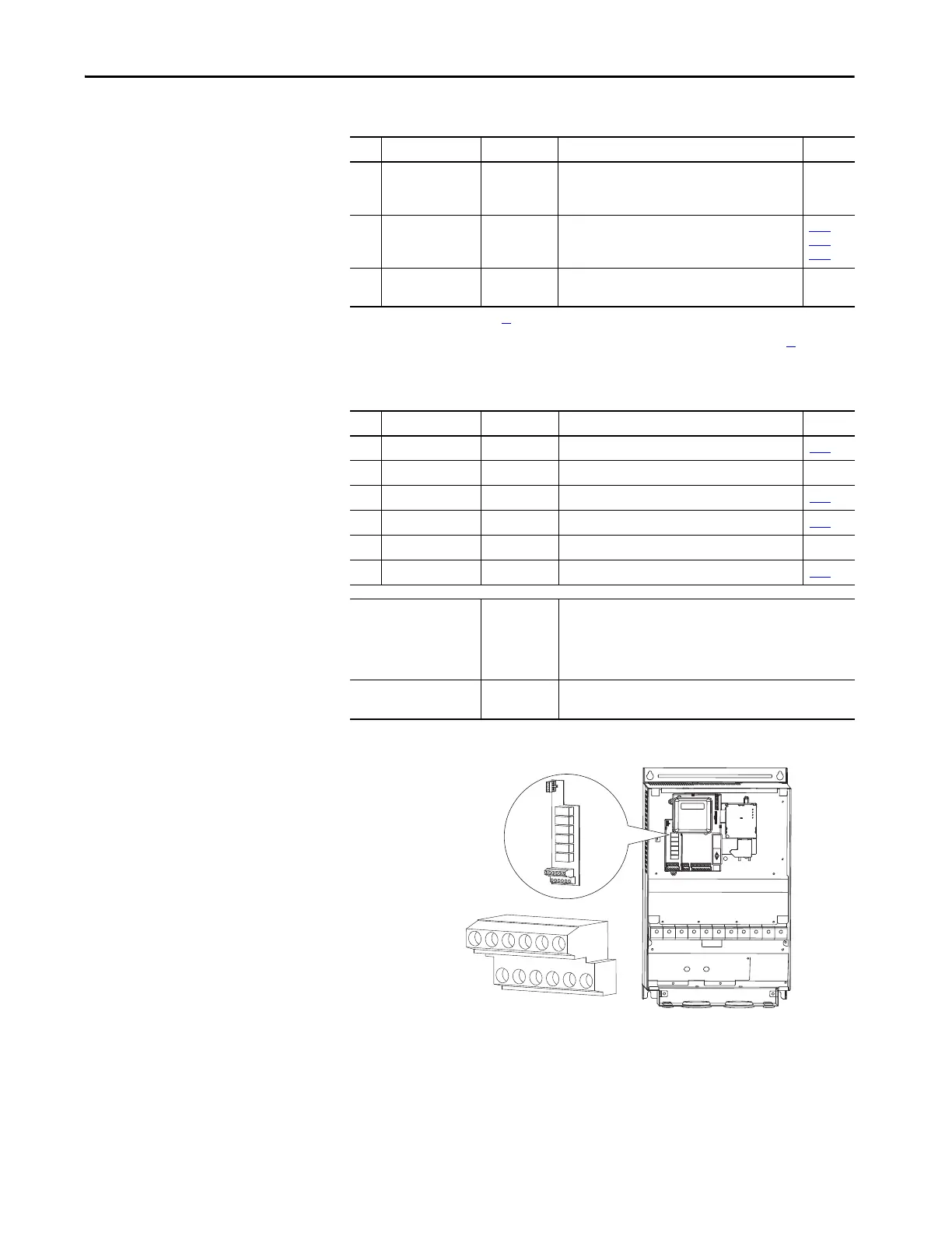
Figure 11 - User Installed Auxiliary Relay Card (Frames D, E, F, G and H Only)
18 Analog Common 2 – For Analog Input 2. Electronically isolated from digital
I/O and opto output. With Analog Input 2, provides
one fully isolated analog input channel.
19 Opto Output At Frequency Program with T065 [Opto Out Sel]. T065
,
T066
,
T068
20 RS485 (DSI) Shield – Terminal connected to Safety Ground - PE when using
the RS485 (DSI) Communication Port.
(1) See Footnotes (1) and (4) on page 29.
(2) Important information regarding Stop commands and the [Digital Inx Sel] Purge option is provided on page 66
.
Table 10 - Relay Terminal Designations and DIP Switches
No. Signal Default Description Param.
R1 #1 Relay N.O. Ready/Fault Normally open contact for No. 1 output relay. T055
R2 #1 Relay Common – Common for output relay.
R3 #1 Relay N.C. Ready/Fault Normally closed contact for No. 1 output relay. T055
R4 #2 Relay N.O. Motor Running Normally open contact for No. 2 output relay. T060
R5 #2 Relay Common – Common for output relay.
R6 #2 Relay N.C. Motor Running Normally closed contact for No. 2 output relay. T060
Selection DIP Switches:
Analog Input (AI1 & AI2)
Analog Output (AO1 & AO2)
0-10V Sets analog output to either voltage or current.
Settings must match: AI1 & T069 [Analog In 1 Sel]
AI2 & T073 [Analog In 2 Sel]
AO1 & T082 [Analog Out1 Sel]
AO2 & T085 [Analog Out2 Sel]
Sink/Source DIP Switch Source (SRC) Inputs can be wired as Sink (SNK) or Source (SRC)
via DIP Switch setting.
Table 9 - Control I/O Terminal Designations
No. Signal Default Description Param.
3A
3B
4A
4B
5A
5B
6A
6B
7A
7B
8A
8B
 Loading...