14 ControlLogix Voltage/Current Input Module
Publication 1756-IN040C-EN-P - October 2000
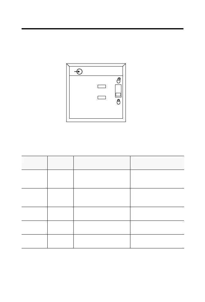
Check the Indicators
The indicators show CAL status (green) and a bi-colored LED for
module "OK" (red/green).
During power up, an indicator test is done and the following occurs:
• The "OK" indicator turns red for 1 second and then turns to
flashing green if it has passed the self-test.
This completes installation of the module. Use the information below
to remove the module.
LED
indicators:
This
display:
Means: Take this action:
OK Steady
green light
The inputs are being
multicast and in normal
operating state.
None
OK Flashing
green light
The module has passed
internal diagnostics but is not
actively controlled.
Configure the module.
OK Flashing red
light
Previously established
communication has timed out.
Check controller and chassis
communication
OK Steady red
light
The module must be replaced. Replace the module.
CAL Flashing
green light
The module is in calibration
mode.
None
20962-M
ANALOG INPUT
CAL
OK
 Loading...


