ControlLogix Voltage/Current Input Module 5
Publication 1756-IN040C-EN-P - October 2000
Note the Power Requirements
This module receives power from the 1756 chasis power supply and
requires 2 sources of power from the backplane:
• 150mA at 5.1V dc
• 40mA at 24V dc
Add this current/power value (1.73W) to the requirements of all other
modules in the chassis to prevent overloading the power supply.
Install the Module
You can install or remove the module while chassis power is applied.
ATTENTION
!
The module is designed to support Removal and
Insertion Under Power (RIUP). However, when
you remove or insert an RTB with field-side power
applied, unintended machine motion or loss of
process control can occur. Exercise extreme
caution when using this feature.
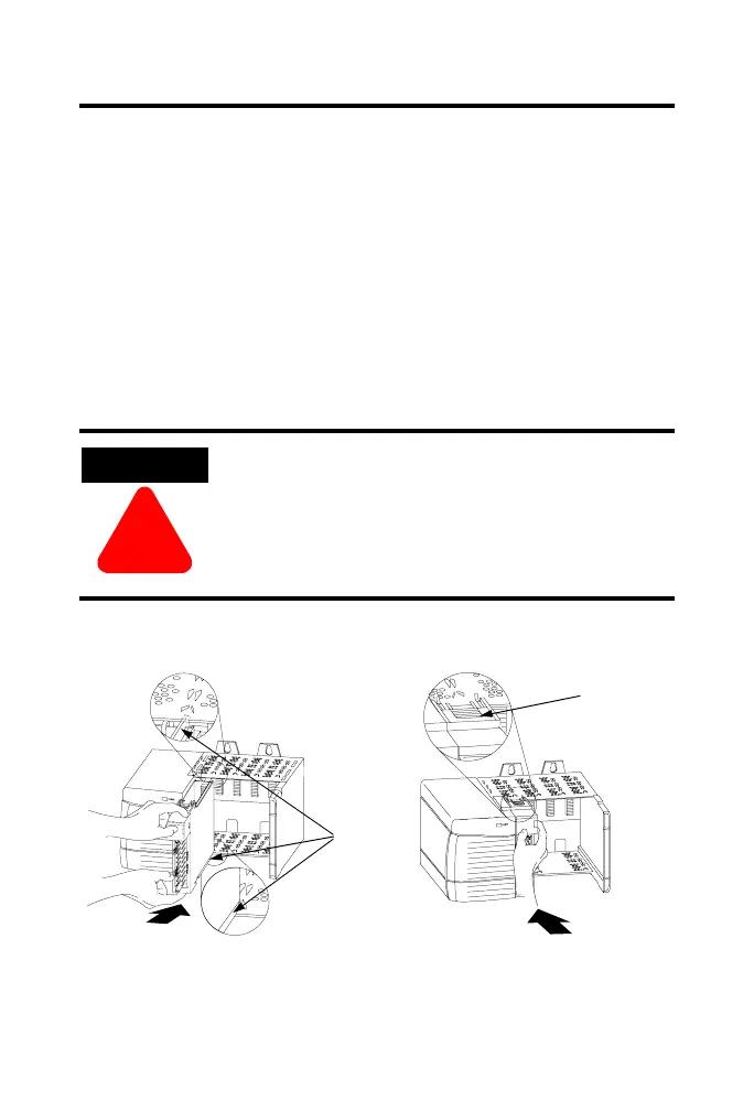
20861–M 20862–M
1. Align circuit board with top and
bottom chassis guides.
2. Slide module into chassis until
module locking tabs ‘click’.
Printed
Circuit
Board
Locking tab
 Loading...


