6 ControlLogix Voltage/Current Input Module
Publication 1756-IN040C-EN-P - October 2000
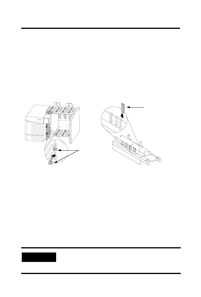
Key the Removable Terminal Block/Interface Module
Wedge-shaped keying tabs and U-shaped keying bands came with
your RTB to prevent connecting the wrong wires to your module.
Key positions on the module that correspond to unkeyed positions
on the RTB. For example, if you key the first position on the module,
leave the first position on the RTB unkeyed.
Reposition the tabs to rekey future module applications.
Wire the Removable Terminal Block
Wire the RTB with a 1/8 inch (3.2mm) maximum flat-bladed
screwdriver before installing it onto the module.
Shielded cable is required when using this module. We recommend
using Belden 8761 cable to wire the RTB. The RTB terminations can
accommodate 14-22 gauge shielded wire.
Connect grounded end of the cable
1. Ground the drain wire.
We recommend grounding the drain wire at the
field-side. If you cannot ground at the field-side, ground
at an earth ground on the chassis as shown.
20850–M
1. Insert the U-shaped band as shown.
2. Push the band until it snaps in place.
U-shaped
bands
1. Insert the wedge-shaped tab with rounded edge first.
2. Push the tab until it stops.
20851–M
Wedge-shaped tab
Key the Module Key the RTB/IFM
 Loading...


