Kinetix 5700 Dual-axis Inverters 3
Rockwell Automation Publication 2198-PC002D-EN-P - November 2017
Ground Screw Installation
Included with the drive module connector set is a ground screw. Install the ground screw for grounded (wye)
power configurations. Do not install the ground screw when using ungrounded, corner-grounded, or
impedance-grounded power, the Bulletin 8720MC regenerative power supply, or any active converter.
We recommend that you install the ground screw when the drive is removed from the panel and placed on its
side on a solid surface equipped as a grounded static-safe workstation.
To access the ground screw on dual-axis inverters, open the small plastic door on the right side of the module.
Install the Ground Screw
Ground Screw Configurations
Mount the Dual-axis Inverter
Observe these clearance requirements when mounting the dual-axis inverter:
• Additional clearance is required for cables and wires or the shared-bus connection system connected to the
top of the drive.
• Additional clearance is required if other devices are installed above and/or below the drive and have
clearance requirements of their own.
• Additional clearance left and right of the drive is required when mounted adjacent to noise sensitive
equipment or clean wire ways.
• The recommended minimum cabinet depth is 300 mm (11.81 in.).
Refer to the Kinetix Servo Drives Technical Data, publication KNX-TD003
, for Kinetix 5700 drive dimensions.
The Kinetix 5700 drive system must be spaced by aligning the zero-stack tab and cutout. For hole patterns, refer
to the Kinetix 5700 Servo Drives User Manual, publication 2198-UM002
.
Mount the Kinetix 5700 servo drives to the cabinet subpanel with M5 (#10-32) steel bolts torqued to 4.0 N•m
(35.4 lb•in), max.
Minimum Clearance Requirements
Connector Data
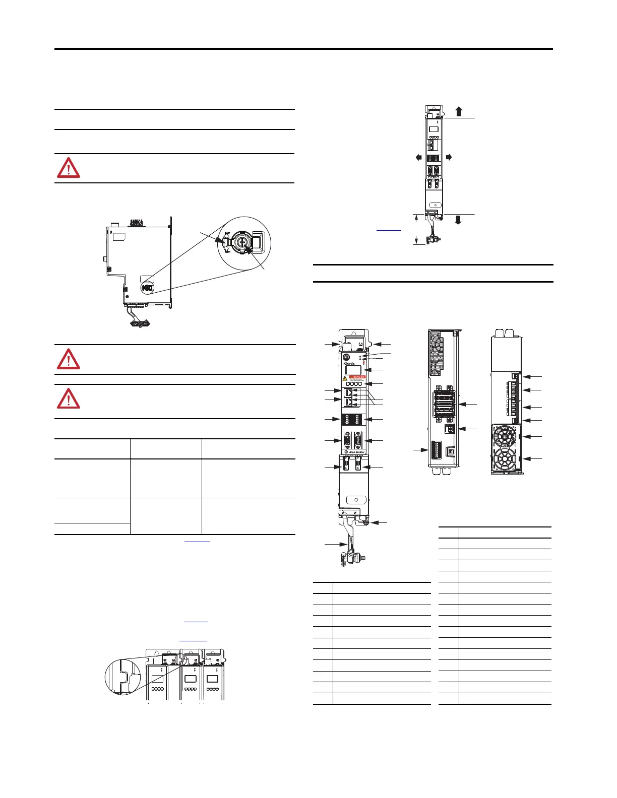
Use this illustration to identify the dual-axis inverter features and indicators.
Dual-axis Inverters Features and Indicators (2198-D006-ERSx inverter is shown)
IMPORTANT
If you have grounded-wye power distribution and 2198-Pxxx DC-bus power supply, install the
ground screw. EMC performance can be affected if the ground screw is not installed.
ATTENTION: When the ground screw is not installed, the risk of equipment damage exists
because the unit no longer maintains line-to-neutral voltage protection.
ATTENTION: To avoid personal injury, the ground screw access door must be kept closed when
power is applied. If power is applied, and then removed, wait at least 5 minutes for the DC-bus
voltage to dissipate, and verify that no DC-bus voltage exists before accessing the ground screw.
ATTENTION: Risk of equipment damage exists. The drive ground configuration must be
accurately determined. Install the ground screw for grounded power configurations. Do not
install the screw for ungrounded, corner-grounded, and impedance-grounded power, or when an
active converter supplies the DC-bus voltage.
Ground Configuration
(1)
(1) Refer to the Kinetix 5700 Servo Drives User Manual, publication 2198-UM002, for example power configurations.
Ground Screw
Configuration
Benefits of Configuration
Grounded (wye) Installed
• UL and EMC compliance
• Reduced electrical noise
• Most stable operation
• Reduced voltage stress on
components and motor bearings
• AC-fed ungrounded
• Corner grounded
• Impedance grounded
Not installed (default setting)
• Helps avoid severe equipment
damage when ground fault occurs
• Reduced leakage current
DC-bus from active converter
Install the ground screw for grounded power
configurations. Do not install the ground screw for
ungrounded, corner-grounded, and impedance-grounded
power or grounded systems with active power supplies
(screw not installed is the default setting).
Ground Screw
Access Door
Ground Screw
Ground Screw
2198-Dxxx-ERSx
Dual-axis Inverter
(side view)
Zero-stack Tab and
Cutout Aligned
Shared-bus connection system
is not shown for clarity.
IMPORTANT Mount the drive in an upright position as shown. Do not mount the drive on its side.
1
I/O-A
6
10
1
I/O-B
6
5
10
UFB-A
UFB-B
D+
D-
D+
D-
MF-A
MF-B
MOD
NET
2
1
5
93 mm
(3.7 in.)
Clearance right of the
drive is not required.
Clearance left of the
drive is not required.
2198-Dxxx-ERSx
Dual-axis Inverter
(front view)
100 mm (3.94 in.) clearance
below drive for airflow and
installation.
40 mm (1.57 in.) clearance above
drive for airflow and installation.
Refer to the Kinetix Servo Drives
Technical Data, publication KNX-TD003
,
for Kinetix 5700 drive dimensions.
22
12
7
9
17
10
14
13
16
2
11
11
8
20
19
25
15
24
21
3
4
6
5
1
23
25
18
1
I/O-A
6
10
1
I/O-B
6
5
10
UFB-A
UFB-B
D+
D-
D+
D-
MF-A
MF-B
2
1
5
DC+
DC–
24V–
24V+
SB+/NC
S1A
SCA
S2A
SB-
S1B
SCB
S2B
1
8
9
16
W-B V-B U-B
MBRK-A
– +
W-A V-A U-A
MBRK-B
– +
MOD–
NET–
5700
2198-Dxxx-ERSx
Dual-axis Inverter
(top view)
2198-Dxxx-ERSx
Dual-axis Inverter
(bottom view)
2198-Dxxx-ERSx
Dual-axis Inverter
(front view)
Item Description
1 Motor cable clamp
2Ground lug
3 Motor feedback (MF) connector - A
4 Motor feedback (MF) connector - B
5 Universal feedback (UFB) connector - A
6 Universal feedback (UFB) connector - B
7 Digital inputs (IOD) connector - A
8 Digital inputs (IOD) connector - B
9 Ethernet (PORT1) RJ45 connector
10 Ethernet (PORT2) RJ45 connector
Item Description
11 Zero-stack mounting tab/cutout
12 Module status indicator
13 Network status indicator
14 LCD display
15 Navigation push buttons
16 Link speed status indicators
17 Link/Activity status indicators
18 Safe torque-off (STO) connector
19 DC bus (DC) connector
20 24V control input power (CP) connector
21 Motor brake (BC) connector - A
22 Motor power (MP) connector - A
23 Motor power (MP) connector - B
24 Motor brake (BC) connector - B
25 Cooling fan
 Loading...


