(31)
DIR 1000587R0002 (Version 02)
3.8. Main functions
3.8.1. Watchdog
LSIG-MM provide certain watchdog functions able to ensure that CB and trip unit faults are managed properly. These functions
are as follows:
- Watchdog for presence of Auxiliary power supply with “plug” icon displayed.
- RATING PLUG validity.
- Watchdog for proper connection of the current sensors (CS). If it is enabled, any anomalies are indicated by a special alarm
message and the “alarm” LED coming on, and the circuit-breaker opens after 1s.
- Watchdog for proper connection of the Trip Coil (TC). If it is enabled, any anomalies are indicated by a special alarm message
and the “alarm” LED coming on.
3.8.2. Circuit-breaker state
LSIG-MM detect the state of the circuit-breaker by means of specifi c wiring in the CB itself. When the presence of current is de-
tected with the circuit-breaker “OPEN”, state error is signalled by means of a warning message and the “warning” led comes on.
3.8.3. Function MM
LSIG-MM has a pair of input and output contacts for managing protection MM, described in par. 3.6.10:
- K14/K15: input for activating protection MM;
The voltage applied between K14 (+) and K15 (-) establishes the state of the protection:
- 0..2Vdc protection deactivated.
- 15..24Vdc protection activated.
Consumption @24Vdc= 3mA max.
- 95S/98S: the output supplies the state of protection MM:
- If the protection is active, the contact is closed;
- If the protection is deactivated, the contact is open.
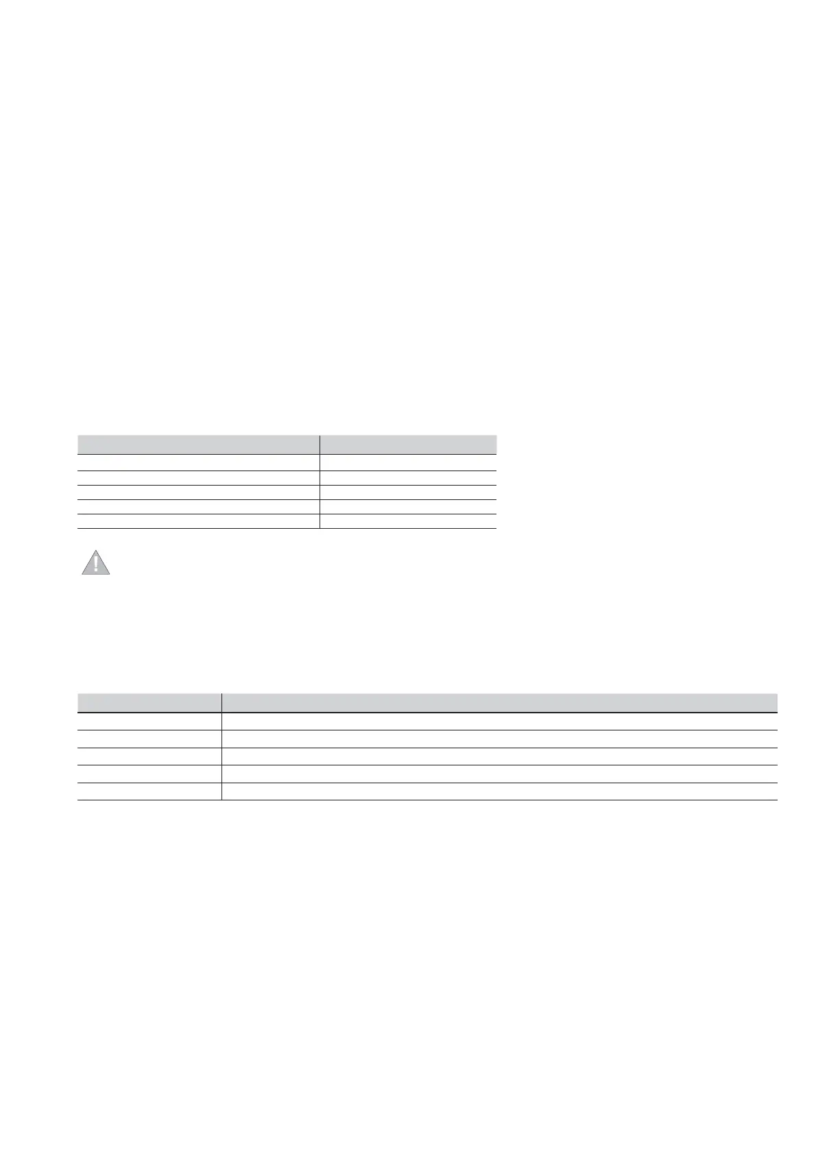
The contact is available in all supply confi gurations and possesses the following electrical characteristics:
Type of contact
Maximum switching voltage 400 Vac (Peak) / Vdc
Maximum switching current 0.1 Aac (Peak) / Adc
Maximum switching power 40 W
Contact/Circuit insulation 1500 Vac
ATTENTION:
-Upon powering, and if there is already energizing voltage on the input contact, the output contact closes within
100 ms.
-Following a trip through protection MM, the output contact can open temporarily for up to 20ms.
3.9. Settings Menu
The Settings menu contains various different settings for trip unit operation and for confi guring the installation in the correct way.
7 options are available:
Settings Menu Options Description
1. Circuit breaker Enabling and adjustment of the Neutral protection, earth protection and the installation commands
2. Mains frequency Adjustment of the frequency of the installation
3. Measurement interval Adjustment of the measurement interval for the log fi le
4. System Date, time, language, password settings
5. Display Contrast Adjustment of the display contrast
3.9.1. Circuit-breaker
This area allows you to:
- Enable the Neutral protection (ON/OFF) and adjust its control level (50%- 100% - 200%). All the details about the operating
mode are given in the description of the Neutral protection, in par. 3.6.9.
- Perform the installation and uninstalling operations for the trip unit in the CB. Instructions for correct installation are given in
par. 3.11.1 and 3.11.2.
3.9.2. Network frequency
This area allows you to enter the frequency of the installation: 50Hz or 60Hz.
Selection of this parameter allows the trip unit to calibrate its protection and measurement functions according to the value
chosen by the user.
3.9.3. Measurement Interval
The storage time for the measurements log fi le can be adjusted in the Settings-Measurement Interval menu. Further details about
the measurements function are given in par. 3.7.4.
 Loading...