(5)
DIR 1000587R0002 (Version 02)
2.2.4. Compatibility CB
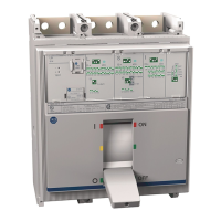
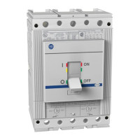
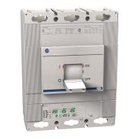
LSIG can be installed in AB circuit-breakers of the three-pole, three-pole with external neutral or four-pole type from the 140G-R,
140G-N and 140G-NS (any size).
The CB model establishes the rated uninterrupted current the circuit-breaker is able to support (lu).
The adjustable protections (L, S, I and G) refer to the In size defi ned by the interchangeable Rating plug module installed on the
actual trip unit.
2.2.5. Standards
LSIG has been designed to operate in accordance with the following international standards:
- IEC 60947-2 Low voltage switchgear and control gear Part 2: Circuit-Breakers.
- UL 489 Molded-Case Circuit-Breaker, Molded-Case Switches and Circuit-Breaker Enclosures
- CSA C22.2 No. 5, Molded-Case Circuit-Breaker, Molded-Case Switches and Circuit-Breaker Enclosures
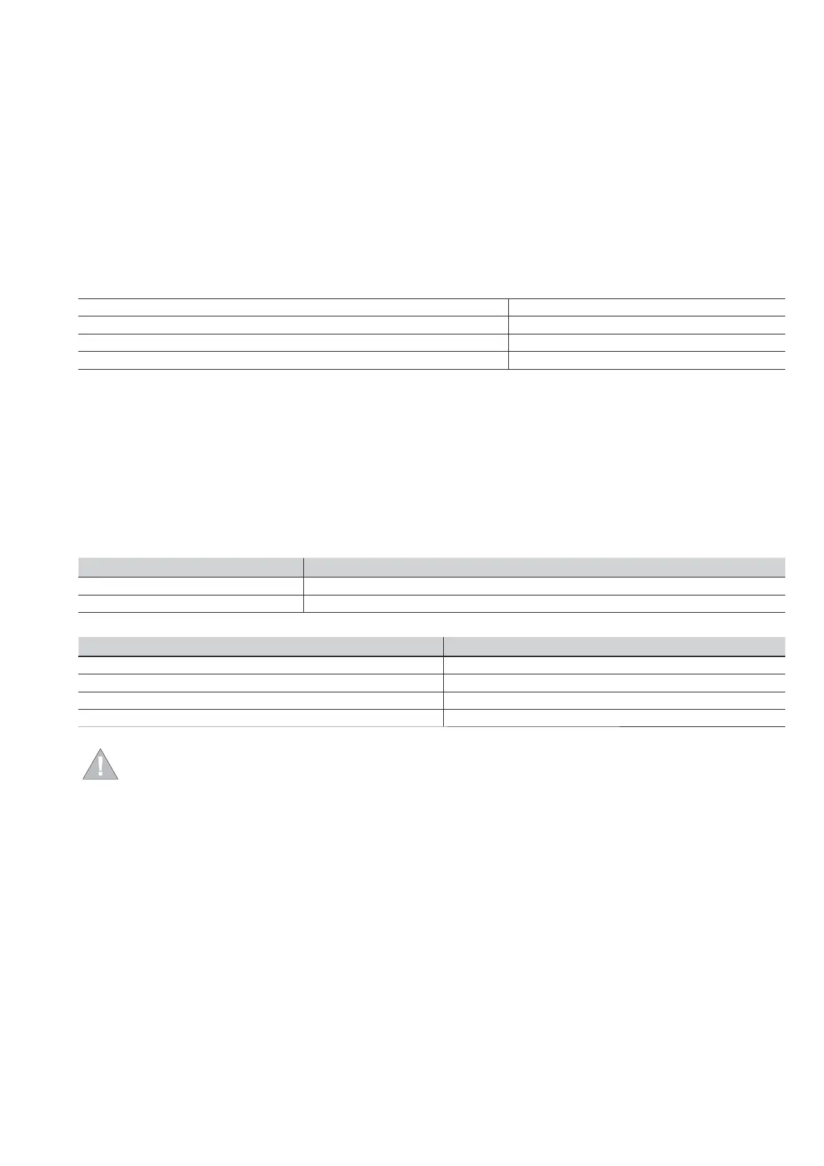
2.2.6. Environmental characteristics
Operating temperature -25 °C ... +70 °C
Storage temperature -40 °C ... +70 °C
Relative humidity 0% ... 98% with condensation
Degree of protection (with LSIG installed in the circuit-breaker) IP 30
2.2.7. Electrical characteristics
The trip unit is energized:
- Directly by the internal current sensors connected to the busbars of each phase. In this case, the trip unit activates with the
circuit-breaker closed and in the presence of a minimum three-phase current value.
- By an external auxiliary power supply. In this case, continuous operation of the unit is guaranteed even with zero current on the
busbars or with the circuit-breaker open.
Note:
Rockwell Automation recommends use of a separate 24V DC power source to power the trip unit. This will eliminate the possibility
of nuisance trips during startup/commissioning when reduced load currents may occur.
Primary current characteristics Range
Minimum three-phase busbar current >80A
Frequency 50/60 Hz ±10%
Auxiliary power supply characteristics Range
DC voltage (galvanically separated) 24 Vdc ±20%
Maximum ripple 5%
Inrush current @ 24V ~2 A for 5ms
Rated power @ 24V ~2 W
ATTENTION: Separate DC power source must be galvanically separated from ground, in accordance with
UL 60950 (IEC 60950) or equivalent IEC 60364-41 [CEI 64-8].
 Loading...