8 Rockwell Automation Publication 2711P-IN001J-EN-P - April 2018
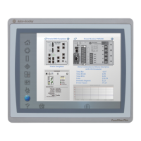
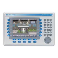
PanelView Plus 700 to 1500 and PanelView Plus Compact 1000 Terminals and Display Modules
Application Information
Per the National Electrical Code the circuit parameters of nonincendive field wiring apparatus
for use in hazardous locations shall be coordinated with the associated nonincendive field wiring
apparatus such that their combination remains nonincendive. The PanelView Plus terminals and
the USB peripheral device shall be treated in this manner.
The circuit parameters of the PanelView Plus USB port are given in Table 1. The USB peripheral
device and its associated cabling shall have circuit parameters with the limits given in Table 2 for
them to remain nonincendive when used with the PanelView Plus USB port. If cable capacitance
and inductance are not known the following values from ANSI/ISA-RP 12.06.01-2003 may be
used:
C
cable
= 197 μF/m (60 μF/ft)
L
cable
= 0.7 μF/m (0.20 μH/ft)
Nonincendive field wiring must be wired and separated in accordance with 501.10(B)(3) of the
National Electrical Code (NEC) ANSI/NFPA 70 or other local codes as applicable.
This associated nonincendive field wiring apparatus has not been evaluated for use in
combination with another associated nonincendive field wiring apparatus.
Wiring and Safety Guidelines
Use publication NFPA 70E, Electrical Safety Requirements for Employee Workplaces, IEC
60364 Electrical Installations in Buildings, or other applicable wiring safety requirements for the
country of installation when wiring the devices. In addition to the NFPA guidelines:
• Connect the device and other similar electronic equipment to its own branch circuit.
• Protect the input power by a fuse or circuit breaker rated at no more than 15 A.
Symbol Definitions
V
oc
Open circuit voltage of the host USB port.
I
sc
Maximum output current of the host USB port.
V
max
Maximum applied voltage rating of the USB peripheral device.
V
max
shall be greater than or equal to V
oc
in Table 1 (V
max
≥ V
oc ).
I
max
Maximum current to which the USB peripheral device can be subjected.
I
max
shall be greater than or equal to I
sc
in Table 1 (I
max
≥ I
sc
).
C
i
Maximum internal capacitance of the USB peripheral device.
C
a
Maximum allowed capacitance of the USB peripheral device and its associated cable. The sum of C
i
of the
USB peripheral device and C
cable
of the associated cable shall be less than or equal to C
a
(C
i
+ C
cable
≤ C
a
).
L
i
Maximum internal inductance of the USB peripheral device.
L
a
Maximum allowed inductance of the USB peripheral device and its associated cable. The sum of L
i
of the
USB peripheral device and L
cable
of the associated cable shall be less than or equal to L
a
(L
i
+ L
cable
≤ L
a
).
 Loading...


