PowerFlex 525 Incremental Encoder Input
Publication 520-IN009C-EN-P - July 2014
Supersedes Publication 520-IN009B-EN-P - September 2013 Copyright © 2014 Rockwell Automation, Inc. All rights reserved.
Allen-Bradley, Rockwell Software, Rockwell Automation, PowerFlex, and TechConnect are trademarks of Rockwell Automation, Inc.
Trademarks not belonging to Rockwell Automation are property of their respective companies.
U.S. Allen-Bradley Drives Technical Support - Tel: (1) 262.512.8176, Fax: (1) 262.512.2222, E-mail: support@drives.ra.rockwell.com
Online: www.ab.com/support/abdrives
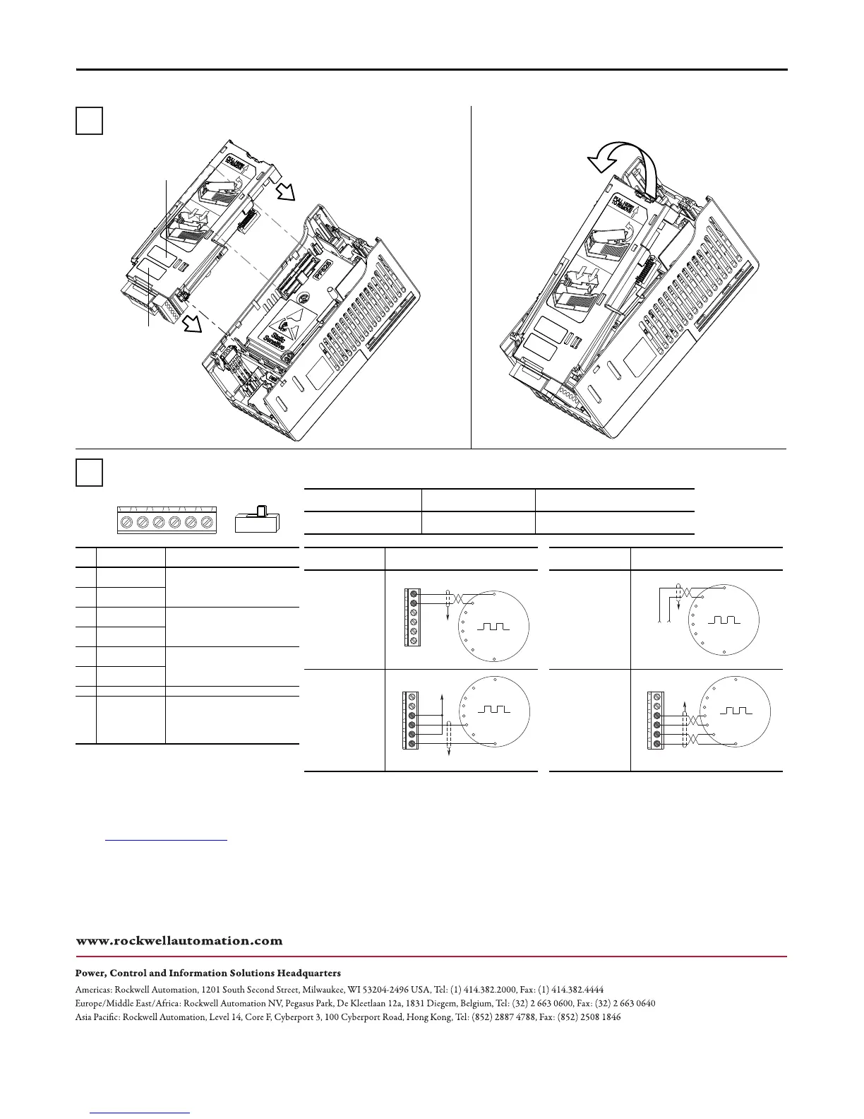
+VCmB-BA-A
12V 5V
No. Signal Description
A Encoder A Single channel, pulse train or
quadrature A input.
A- Encoder A (NOT)
B Encoder B Quadrature B input.
B- Encoder B (NOT)
Cm Power Return Internal power source 250 mA
(isolated).
+V 5...12V Power
(1)
(1) If Encoder requires 24V power, it must be supplied by an
external power source.
Output DIP switch selects 12 or 5 volt
power supplied at terminals
“+V” and “Cm” for the encoder.
I/O Connection Example I/O Connection Example
Encoder Power
– Internal Drive
Power
Internal (drive)
12V DC, 250mA
Encoder Power
– External
Power Source
Encoder Signal
– Single-Ended,
Dual Channel
Encoder Signal
– Differential,
Dual Channel
Common
+12V DC
(250 mA)
A
A-
B
B-
Cm
+V
to SHLD
+
Common
External
Power
Supply
to
SHLD
A NOT
A
B
B NOT
to SHLD
to Power Supply
Common
A
A-
B
B-
Cm
+V
to SHLD
A NOT
B
A
B NOT
A
A-
B
B-
Cm
+V
Wiring the Incremental Encoder
Attach the Control Module Back Cover
How to Remove the Control Module Back Cover if Required
Maximum Wire Size Minimum Wire Size Torque
2.08 mm
2
(14 AWG) 0.08 mm
2
(28 AWG) 0.18...0.22 Nm (1.56...1.9 lb-in)
Incremental Encoder Input with optional
25-COMM-D DeviceNet adapter shown
Incremental Encoder Input
label (pre-attached)
Space for optional
communication adapter label

 Loading...


