Behavior models used in CIP Motion
36 Rockwell Automation Publication MOTION-RM003I-EN-P - February 2018
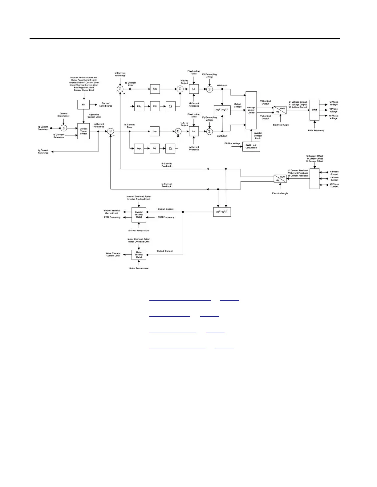
The following diagrams show an overview of this behavior model.
See also
Current Vector Limiter on page 36
Voltage Output on page 37
Current Feedback on page 37
Motor Commutation on page 38
The Iq Current Command passes through a Current Vector Limiter before
becoming the Iq Current Reference signal. This limiter computes the combined
vector magnitude of the Iq Current Reference and the Id Current Reference
signals. The resultant current vector magnitude is compared to the Operative
Current Limit that represents the minimum current limit from among a set of
potential current limits of the drive device and motor.
If the vector magnitude exceeds the Operative Current Limit, the Iq Current
Reference is reduced so the vector magnitude equals the Operative Current Limit.
Potential current limit sources can be the Peak Current Limit ratings as well as the

 Loading...


