4 PowerFlex 755 On-Machine Packaged Drive
Rockwell Automation Publication 750-PC004B-EN-P - April 2019
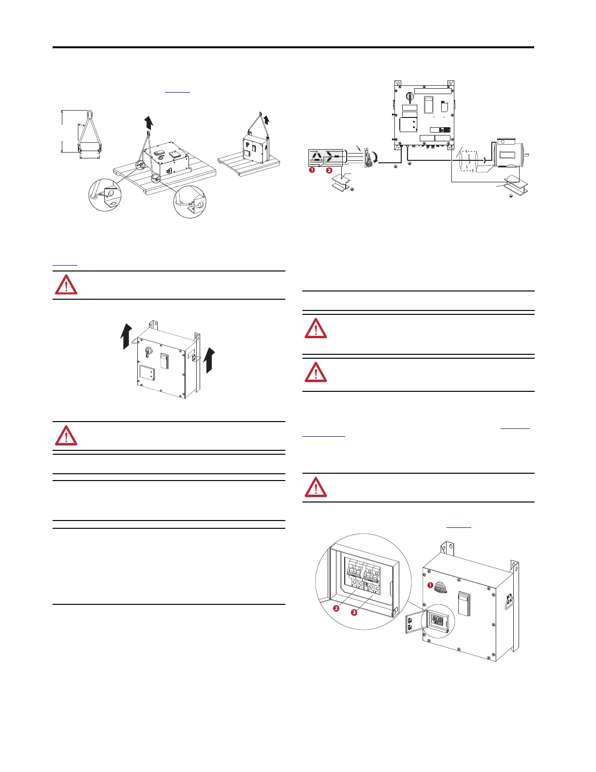
Hoist Lifting
For more information on lifting and transporting the On-Machine Packaged Drive, see PowerFlex 755
On-Machine Packaged Drive User Manual, publication 750-UM006
.
Two-Person Lifting
The On-Machine Packaged Drive has a weight greater than 45.36 kg (100 lbs). As a result, it is required to have
two people when using the handles to lift the drive. For more information on lifting and transporting the
On-Machine Packaged Drive, see PowerFlex 755 On-Machine Packaged Drive User Manual, publication
750-UM006
.
Wiring, Grounding, and Packaged Drive Power
Circuit Protection
Branch circuit protection for the On-Machine Packaged Drive is provided by the internal circuit breaker. The
feeder available fault current must not exceed 65,000 A RMS symmetrical at 480V AC. Input feeder power fuse
and/or circuit breaker protection is required for the M35 input connector and the customer must provide it based
on NEC guidelines and specific local codes.
Feeder Circuit Protection
1. From user-supplied 400/480V AC, 3-phase, 50/60-Hz delta-Wye connected power distribution with solidly grounded neutral.
2. If the user-supplied input power distribution exceeds 20 times drive rating kVA, additional impedance must be supplied in the
form of an input line reactor or isolation transformer.
Short-circuit current rating (SCCR)
The short circuit rating for the On-Machine Packaged Drive is 65,000A RMS at 480V AC. The suitable circuit
breaker for this circuit must be capable of delivering not more than 65,000 RMS symmetrical amperes at 480V
AC, 100 A maximum, when protected by a Bulletin 140G-H frame circuit breaker. Also, the suitable fuses for this
circuit must be capable of delivering not more than 65,000 RMS symmetrical amperes at 480V AC maximum
when protected by CC, J, and T classes.
Branch Circuit Protection
Circuit Breakers
The packaged drive has three circuit breakers that are accessible on the front cover. All three circuit breakers
must be ON for the drive to operate and control the motor and brake properly. The 400/480V AC main input
rotary circuit breaker provides power through the M35 power connector (Receptacle L123). See Feeder Circuit
Protection on page 4 for more information.
The mechanical brake circuit breaker and the control power circuit breaker are located under the auxiliary circuit
breaker door and are provided power by Receptacles CP (24V DC auxiliary power), CPBR (24V DC brake option B2
and B3), and L123 (source brake option SB). The brake circuit breaker will vary in design and operation based on
it being a 24V DC mechanical brake or 480V source mechanical brake.
A visual inspection can verify that the breakers are individually opened or closed. For information on how to
open the auxiliary circuit breaker door and more details about the circuit breaker reset procedures, see
PowerFlex 755 On-Machine Packaged Drive User Manual, publication 750-UM006
.
1. 400/480V AC rotary power disconnect
2. 24V DC mechanical brake circuit breaker (shown) or 480V source mechanical brake circuit breaker
3. 24V DC control power circuit breaker
ATTENTION: Hazard of personal injury and machine damage exists. Do not attach lifting straps to
the handles.
ATTENTION: A hazard of personal injury and equipment damage exists. A minimum of 10 AWG
should be used for the solid earth ground.
IMPORTANT The safety ground, PE, must be connected to earth ground. Some codes may require
redundant ground paths and periodic examination of connection integrity.
IMPORTANT To avoid electrolytic corrosion on the external earth terminal, avoid spraying moisture
directly on the terminal. When used in washdown environments, apply a sealant or
other corrosion inhibitor on the external ground terminal to minimize any negative
effects of galvanic or electro-chemical corrosion. Ground connections should be
inspected regularly.
IMPORTANT For compatibility, the motor cable connector that is selected must provide good 360°
contact and low transfer impedance from the shield or armor of the cable to the conduit
entry plate at both the motor and the On-Machine Packaged Drive, for electrical
bonding.
The motor cable should be kept as short as possible to avoid electromagnetic emissions
and capacitive currents. CE conformity of On-Machine Packaged Drive with EMC Directive
does not confirm that the entire machine installation complies with CE EMC
requirements.
See the National Electrical Code (NEC) NFPA 70 and/or the Electrical Standard
for Industrial Machinery NFPA79 for proper installation details.
Dimensions are in millimeters and (inches).
IMPORTANT The motor branch circuit protection is provided by the main circuit breaker, which
complies with UL508 and CSA guidelines.
WARNING: Circumstances that can cause an explosion may exist, which may lead to personal
injury or death, property damage, or economic loss. If the branch circuit protection device trips,
you must use the software to verify that the source brake function is still operational before
putting the equipment back in service. If the source brake function is not working properly, loss of
brake function or motor damage can occur.
WARNING: Circumstances that can cause an explosion may exist, which may lead to personal
injury or death, property damage, or economic loss. Do not install the On-Machine Packaged
Drive where the maximum available fault current exceeds the 65,000 A RMS symmetrical
amperes.
ATTENTION: Do not cycle 400/480V AC power more frequently than one cycle every 1 minute.
Failure to comply will result in serious equipment damage.
U (T1)
V (T2)
W (T3)
SHLD
Exposed Structure
and/or Building Steel
Shielded
Motor Cable
M35
R (L1)
S (L2)
T (L3)
Maximum
65,000 A SCCR
Exposed Structure
and/or Building Steel

 Loading...


