ITA ENG FRA ESP DEU POR
2 / 16
6-1622158 REV.01 27/07/2012
WARNING: DO NOT INSTALL THE CONTROL UNIT WITHOUT READING THE INSTRUCTIONS FIRST!
The B1EE ERMES2 control unit is a universal equipment suitable for easily handling the functioning and control of sliding and bascule doors ; it Is
developed to satisfy all requirements. This product controls 230V motors in alternating current up to 600W of power, both with and without encoder.
This control unit can decode the traditional fix code system and the safest and innovative Rolling code system through the special receiver selection
switch. Each control owns a memory module which allows to memorize up to 1000 different transmitters, both fix and rolling code.
1. Introduction
2. Configuration
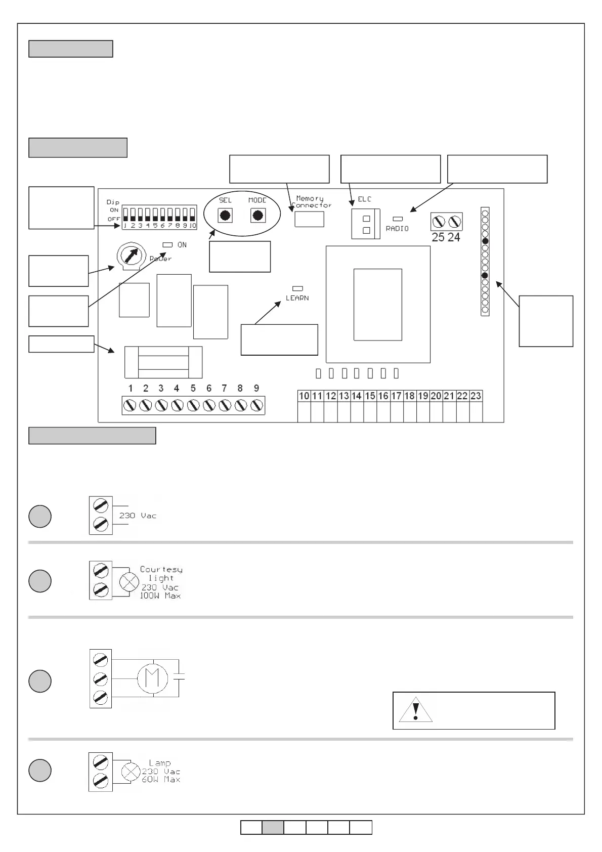
Learning led
Turning on
led
6.3A Fuse
Dip-Switch
Function
selection
SEL and
MODE keys
Radio
module
connector
Torque
adjuster
3. Electrical wiring
2
3
4
Motor condenser 230 Vac
!Risk of electric shock!
Connect the motor condenser between
clamps 5 and 7 of the control unit
The control unit is supplied with all normally closed inputs jumpered to the common. Before connecting a
safety device to the control unit, you must remove the jumper of the safety device to be wired by leaving
untouched all other safety devices.
R1 electric lock card
connector
Extractable memory
connector
Diagnostic radio
interferences led
Power supply 230 Vac 50 Hz
Do not connect the card directly to the electric net-
work. Put a device which can ensure the disconnec-
tion of each pole from the power supply of the control
unit.
1
Connect the power supply cable between
clamp 1 and 2 of the control unit
Connect an eventual courtesy light between
clamp 3 and 4 of the control unit.
It is possible to light up the action area of the autom-
atism during each motions by connecting a charge
of max 230Vac 100W. The turning off is timed 1
minute after the stop of the automation.
The courtesy light shortly blinks during the photocell
test (if connected).
1
2
3
4
•
Connect the neutral of the motor to
clamp 6 of the control unit.
•
Connect phase “1” of the motor to
clamp 5 of the control unit.
•
Connect phase “2” of the motor to
clamp 7 of the control unit.
Before programming the strokes, check the correct
wiring of the motor and the limit switches that must
correspond to the installation manual. Follow the
procedures of the preliminary checks for doing
that.
6
5
7
COM
F1
F2
Connect the flashing light between clamps 8
and 9 of the control unit. The connected
flashing light must have a maximum power of
60W at 230 Vac.
WARNING: connect a B.RO LIGHT FIX flashing
light (without self-flashing card)
8
9
COM S.S. Photo Stop Edge L.s.cl L.s.op. Ped.
L
N
 Loading...