ITA ENG FRA ESP DEU POR
2 / 12
6-1622189 rev.1 22/05/2015
Compatible from firmware version BIOS2BT02
1. Introduzione
ATTENTION: DO NOT INSTALL THE CONTROL UNIT WITHOUT READING THE INSTRUCTIONS FIRST !!!
THE INSTALLATION SHOULD BE PERFORMED ONLY BY QUALIFIED PERSONNEL.
2. Configuration
The control unit BIOS2 is particularly indicated for the installation of 1 or 2 wing gates with 230 Vac motors with maximum power absorbed of
700W.The control unit equipped with a display that allows a precise regulation of the thrust of the gates and sensitivity. It is also possible to adjust the
delay in closure of the second wing in the base settings menu. The control unit can memorize up to 8000 transmitters with the external memory, with
the step by step, pedestrian, open and close functions. It is supplied with inputs for interior and exterior photocell, safety edge (mechanical or 8k2),
possibility to connect the buttons for step by step, pedestrian, open, close and stop. The outputs include a 230 Vac flashing light, electrical lock 12 Vac
15 VA or by the expansion card R1 (not supplied) with dry contact 230 Vac 5A max/30 Vdc 5A max, courtesy light/zone light/open gate light, 24 Vac/dc
accessories power supply.
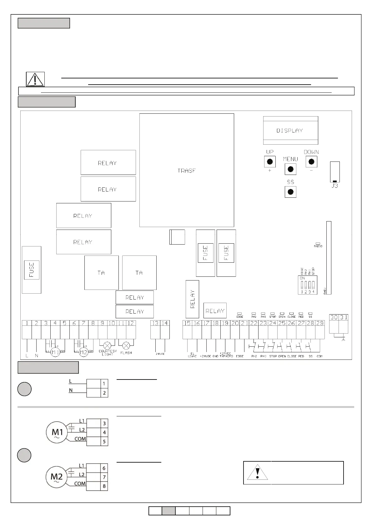
3. Connections
1
POWER SUPPLY
Connect the power supply cable between clamp
1 and 2 of the control unit
Power supply 230 Vac 50 Hz
Do not connect the card directly to the electric
network. Put a device which can ensure the
disconnection of each pole from the power supply of
the control unit.
2
MOTOR 1 OUTPUT
Connect the common of the motor 1 to the
clamp 5 of the control unit.
Connect the phase 1 of the motor 1 to the
clamp 3 of the control unit.
Connect the phase 2 of the motor 1 to the
clamp 4 of the control unit.
MOTOR 2 OUTPUT
Connect the common of the motor 2 to the
clamp 8 of the control unit.
Connect the phase 1 of the motor 2 to the
clamp 6 of the control unit.
Connect the phase 2 of the motor 2 to the
clamp 7 of the control unit.
Motor condensers 230 Vac
!Risk of electric shock!
Connect to the MOTOR 1 output the wing which
beats.Install an aventual electrical lock on this wing.
MOTOR 1 is always activated first during opening
phase and in second during closing phase.
Line FUSE
F 6.3 A
Vac accessories
FUSE
F 2 A
Vdc accessories
FUSE
F 0.5 A
SAFETY
DEVICES
DIP SWITCH
MEMORY
For a correct functioning of the system, it is absolutely indispensable the use of mechanical stops in opening and closing.
 Loading...