COMPONENTS
Sel f -Cl e aning Ro ti s ser i e O v e n ▪ Ser v i ce M anual ▪ MN- 392 4 3 ▪ Rev 1 ▪ 2/19
33
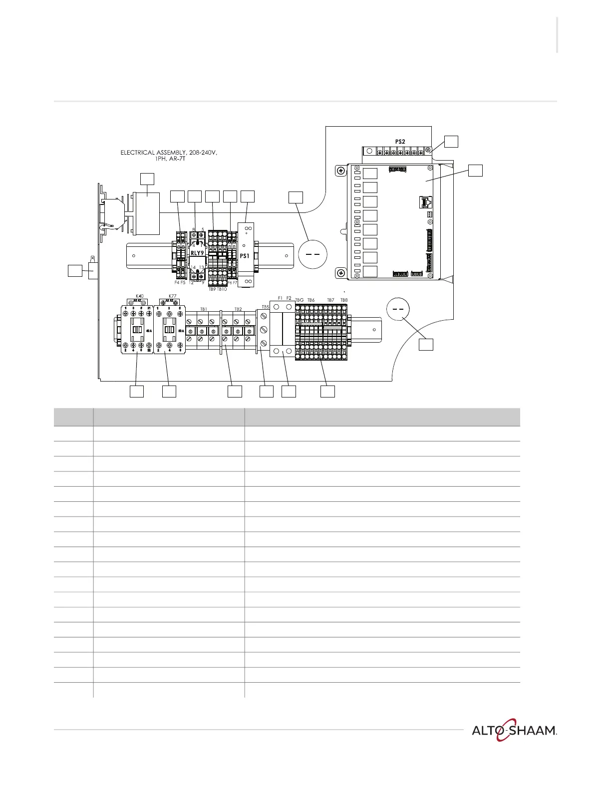
Electrical Chassis — 208-240 volt, 1 phase
Ref. Electrical Schematic Identifier Description
1 C1 Capacitor, spit motor
2 SSR Solid state relay
3 - -
4 F4, F5 Fuses, lights
5 RLY 9 Relay, browning valve
6 TB 9, TB 10 Terminal blocks, DC voltage output from PS1
7 F6, F7 Fuses, DC voltage output from PS1
8 PS1 DC power supply 1
9 C2 Capacitor, convection motor
10 PS2 DC power supply 2
11 Control board Control board (CB)
12 C3
Capacitor, wash pump
13 TBG, TB6, TB7, TB8 Terminal blocks
14 F1, F2 Fuses, line voltage
15 TB5 Terminal block, electrical supply ground connection
16 TB1, TB2 Terminal blocks, electrical supply line connections
17 K-77 Safety contactor
18 K-40 Heat contactor
-
L
N
L1 L2
AR-PHD-005915
1
2
4 5 6 7 8
9
10
11
12
131415
161718
 Loading...