EasyManua.ls Logo

AOC i2252VWH User Manual

AOC i2252VWH
68 pages
To Next Page IconTo Next Page
To Previous Page IconTo Previous Page
Page #28 background image
Service Manual AOCi2252VW
28
5.3 Converter Board 715G4013-P02
ON/ OF F
R808
1K 1/10W
CN802
CONN
1
2
3
4
CN803
NC
1
2
3
4
5
6
7
8
9
10
1112
R810
20K 1/10W
R843
0 OHM +-5% 1/8W
C806
100pF 50V
DIM
R804
100K 1/10W
R817
0.15 OHM +-1% 1/4W
R826 NC
R839
3R3 1%
R819
33K 1/10W 1%
R807
20K 1/10W
R829
NC
R812
0.15 OHM +-1% 1/4W
R822
NC
R828
NC
R832
1 OHM +-5% 1/8W
R825
NC
R846
0 OHM +-5% 1/8W
Gate
DR
R827
NC
+
C807
33UF 100V
C805
100pF 50V
Q801
NC
R809
6.8KOHM +-1% 1/10W
R852
0 OHM +-5% 1/8W
C808
NC
DIM
Q804
NC
CN801
CONN
1
2
3
4
5
6
7
+
C809
100uF 50V
R842 0 OHM +-5% 1/8W
R816
0.15 OHM +-1% 1/4W
R844
0 OHM +-5% 1/8W
R837
NC
LNPCAA481GQCF
B
Custom
12Monday, October 25, 2010
715G4013P0B0020040
OD M MOD EL
01.CONVERTER
G4013-P0E-002-0040-6-100921
OEM MODEL Size
Rev
Date
Sheet
of
TPV MODEL
PCB NAME
称爹
T P V ( Top Victory Elec tronics C o . , Ltd. )
Key Component
R840
NC
R824
NC
D801
3A/100V
1 2
R838
NC
L801
22uH
DR
R811
1K 1/8W
C801
470N 25V
R815
1K 1/8W
R853
0 OHM +-5% 1/8W
R818
0R05 1/4W
R833
NC
DR
R823
NC
R834
1 OHM +-5% 1/8W
R841
0 OHM +-5% 1/8W
R821
NC
U801
MP3389EF
1
2
3
4
5
6
7
8
9
10
11
12
13
14 15
16
17
18
19
20
21
22
23
24
25
26
27
28
29
NC
VIN
VCC
COMP
EN
DBRT
GND
OSC
ISET
BOSC
LED12
LED11
LED10
LED9 LED8
LED7
LED6
LED5
LED4
LED3
LED2
LED1
OVP
ISENSE
PGND
GATE
VFAULT
NC
E-Pad
OVP
R801
10 OHM 1% 1/4W
Q805
NC
R820
NC
Q803
NC
OVP
R803
33K 1/10W 1%
R831
NC
Q806
APM8005K
1
2
3
4 5
6
7
8
S2
G2
S1
G1 D1
D1
D2
D2
CN804
NC
1
2
3
4
5
6
7
8
9
10
1112
CN805
CONN
1
2
3
4
5
6
78
R848
0 OHM +-5% 1/8W
+14. 5V
R847 0 OHM +-5% 1/8W
ON/ OF F
R836
NC
Gate
C803
470N 25V
F801
0R05 4A 1/4W
R802
180K 1/10W 1%
R835
NC
R830
NC
R845
0 OHM +-5% 1/8W
C804
470N 25V
+14.5V
R806
1K 1/10W
Q802
NC
C802
68NF 50V
R805
300K +-1% 1/8W
Question and Answer IconNeed help?

Do you have a question about the AOC i2252VWH and is the answer not in the manual?

AOC i2252VWH Specifications

General IconGeneral
Screen Size21.5 inches
Resolution1920 x 1080
Panel TypeTN
Brightness250 cd/m²
Contrast Ratio1000:1
Response Time5 ms
Refresh Rate60 Hz
ConnectivityVGA, DVI
Dynamic Contrast Ratio20, 000, 000:1
Viewing Angle170° (H) / 160° (V)
Aspect Ratio16:9

Summary

LCD Display Service Manual

Model Identification: i2252VWH

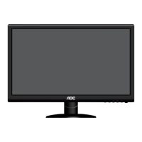
Specifies the monitor model number for service.

Mainboard Compatibility

Details the mainboard compatibility for the manual.

Revision History

Revision A00 Details

Indicates the initial release version, date, and associated model/editor.

1. LCD Specifications

1.1 Product Features Overview

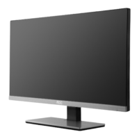
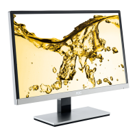
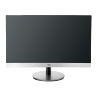
Details the key features and specifications of the LCD monitor.

1.2 Factory Preset Modes

Lists the predefined display modes and their frequency ranges.

1. LCD Specifications

1.1 Product Features - Panel and Signals

Details monitor features, panel specs, input signals, power, and dimensions.

1. LCD Specifications

1.2 Factory Preset Modes Listing

Lists predefined display modes with resolutions and frequencies.

1.3 New Feature Highlights

Highlights new functionalities like Active matrix LCD, LED backlight, and Clear Vision.

1. LCD Specifications

1.4 VGA 15-pin Connector Pinout

Details the pin assignment and layout for the VGA 15-pin connector.

1.5 DVI Connector Pinout

Describes the pinout and layout for the DVI connector.

1. LCD Specifications

1.6 HDMI Interface Pinout

Explains the pin assignment and layout for the HDMI connector.

2. Operation Instruction

2.1 Connection Guide

Guides on how to connect the monitor to a PC and power source.

2.2 Control Button Functions

Describes the function of each control button on the monitor.

2. Operation Instruction

2.3 OSD User Mode Adjustment

Explains how to navigate and adjust settings within the On-Screen Display (OSD).

2. Operation Instruction

OSD Image & Color Setup

Details adjustments for Image Setup, Color Setup, and Picture Boost within the OSD.

2. Operation Instruction

OSD System & Input Settings

Covers OSD settings for Language, Luminance, Image Ratio, and DDC/CI.

2. Operation Instruction

Hotkey OSD Menu Functions

Illustrates functions accessed via hotkeys: Source Selection, Volume, Clear Vision.

2.4 OSD Locked

OSD Lock/Unlock Procedure

Explains how to lock and unlock the OSD menu using button combinations.

3. Panel Feature

3.1 General Panel Specifications

Provides general technical specifications of the LCD panel.

3.2 Electrical Absolute Ratings

Lists the absolute maximum ratings for electrical parameters of the panel.

3. Panel Feature

3.3 Electrical Characteristics

Details the electrical characteristics of the panel module and LED array.

3.4 TFT LCD Module Block Diagram

Shows the block diagram for the TFT LCD module.

3. Panel Feature

3.5 LCD Input Terminal Pin Assignment

Lists the pin assignments for the LCD module's input terminals.

3.6 LED Connector Interface

Describes the pin configuration for the LED connector on the backlight unit.

4. Block Diagram

4.1 LCD Block Diagram

Presents the overall block diagram for the LCD monitor system.

4.2 MainBoard Block Diagram

Details the block diagram of the mainboard, including MCU and interfaces.

4. Block Diagram

4.3 Power Board Block Diagram

Illustrates the block diagram of the power board.

4. Block Diagram

4.4 Software Flow Chart

Displays the software flow chart for the monitor's operation.

5. Circuit Schematic

5.1 Main Board 715G4641M01 Schematic

Provides the circuit schematic for the mainboard.

5. Circuit Schematic

Input Part - VGA+DVI+/DDC Schematic

Shows the schematic for the input signal processing part.

5. Circuit Schematic

HDMI Input Schematic

Details the circuit schematic for the HDMI input section.

5. Circuit Schematic

Power Part - 5V/3.3V/1.8V Schematic

Presents the schematic for the power supply sections.

5. Circuit Schematic

MCU-Scarlar NT68677 Schematic

Shows the schematic related to the MCU and scaler.

5. Circuit Schematic

Output - LVDS Connector Schematic

Illustrates the schematic for the LVDS output connector.

5. Circuit Schematic

Audio Circuit Schematic

Details the audio circuit schematic.

5.2 Power Board 715G4750-P02

Power Board Adapter 16V/5V Schematic

Provides the schematic for the power board's adapter section.

5.3 Converter Board 715G4013-P02

Converter Board Schematic

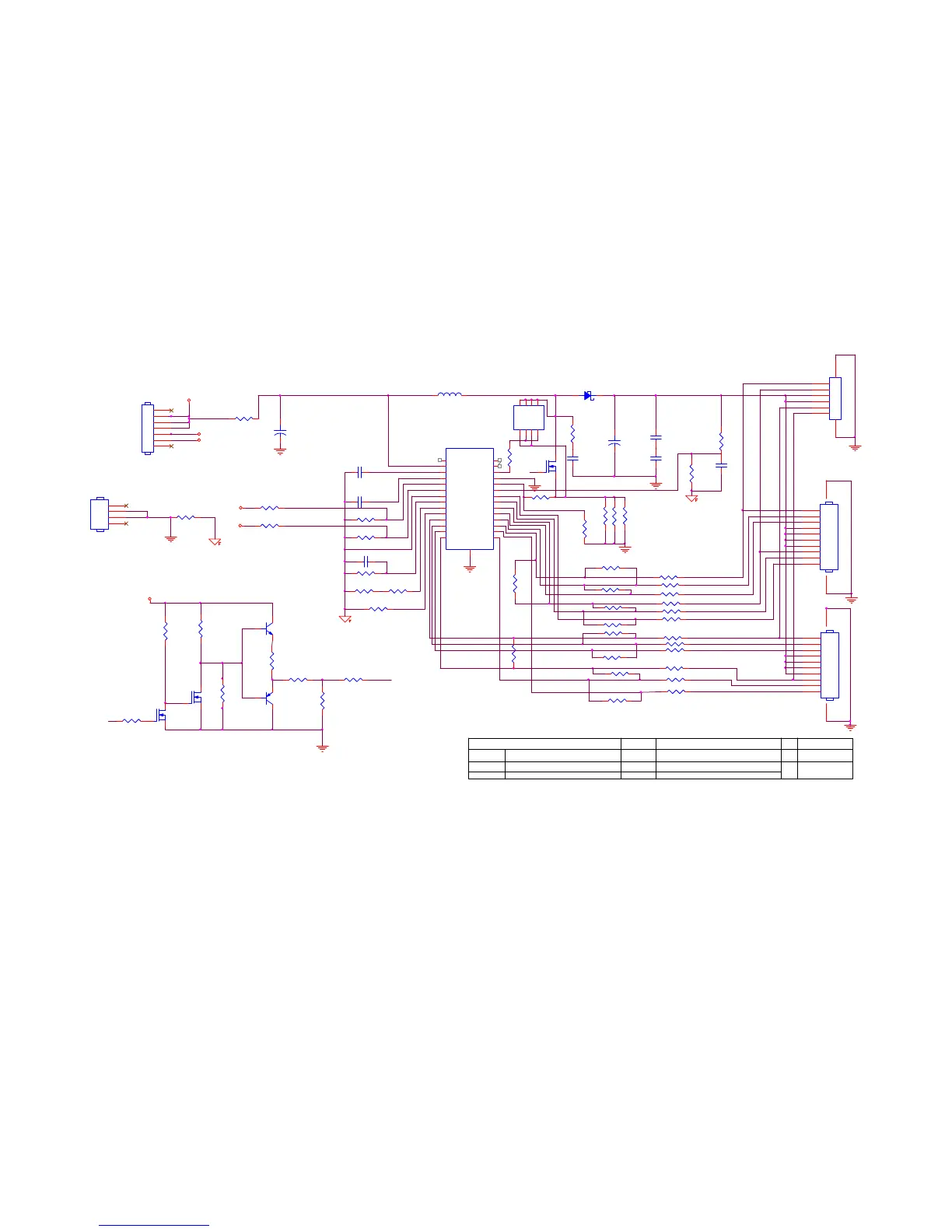
Shows the schematic for the converter board.

5.4 Key Board 715G4851k

Key Board Schematic

Details the schematic for the key board.

6. Monitor Exploded View

Main Component List

Lists the main components with part numbers and quantities for the exploded view.

7. PCB Layout

7.1 MainBoard 715G4641-M01 Layout

Shows the PCB layout for the mainboard.

7. PCB Layout

MainBoard PCB Layout Details

Provides further details of the mainboard's PCB layout.

7. PCB Layout

7.2 PowerBoard 715G4750-P02 Layout

Shows the PCB layout for the power board.

7. PCB Layout

PowerBoard PCB Layout Images

Displays images of the power board's PCB layout.

7. PCB Layout

7.3 Converter Board 1-715G4013P02 Layout

Shows the PCB layout for the converter board.

7. PCB Layout

7.4 KeyBoard715G4851 PCB Layout

Displays the PCB layout for the keyboard.

8. Maintenance

8.1 Maintainability Requirements

Lists the tools and requirements for maintaining the monitor.

8.2 Disassembly SOP Tools

Identifies the specific tools needed for the disassembly procedure.

8. Maintenance

8.2 Disassembly SOP Steps

Illustrates the steps for disassembling the monitor.

8. Maintenance

Internal Component Images

Shows images of internal components during maintenance.

8.3 Troubleshooting

Main Board - No Power Troubleshooting

Provides a flow chart for troubleshooting no power issues on the main board.

8.3 Troubleshooting

No Picture & Whitescreen Troubleshooting

Offers flow charts for no picture and whitescreen issues.

8.3 Troubleshooting

Power Board - No Power Troubleshooting

Guides troubleshooting for no power on the power board.

8.3 Troubleshooting

No Backlight Troubleshooting

Provides a flow chart for troubleshooting backlight issues.

8.3 Troubleshooting

Key Board - OSD No Working Troubleshooting

Offers a flow chart for OSD issues related to the key board.

8.4 Software Update Steps

Product Information for Update

Lists product information relevant to software updates.

Step 1: Connection for Update

Details the connection steps for the software update process.

8.4 Software Update Steps

Step 2: Installing Driver Software

Explains how to install the necessary driver software for the update.

8.4 Software Update Steps

Step 3: Running the Update Tool

Guides on running the Novatek EasyWriter tool for software updates.

8.4 Software Update Steps

Configuring the Update Tool

Details configuration options within the update tool, including Jig type selection.

8.4 Software Update Steps

Setting Up ISP Tool Pins

Explains how to select and configure WP pin settings in the ISP tool.

8.4 Software Update Steps

Executing ISP ON and Loading File

Describes the process of activating ISP ON and loading the software file.

8.4 Software Update Steps

Step 6: Auto-Start Programming

Details the auto-start programming sequence.

8.5 Re-Writing DDC Program Step

DDC Rewriting Procedure

Explains steps for rewriting DDC program after board/panel replacement.

8.5 Re-Writing DDC Program Step

DDC EDID Beijing Tool Usage

Guides on using the DDC EDID tool for EEPROM programming.

8.5 Re-Writing DDC Program Step

Verifying DDC/EDID Settings

Shows how to verify DDC/EDID settings after programming.

8.6 Factory Mode Adjustment

Entering Factory Mode

Explains the procedure to enter the monitor's factory mode.

Factory Mode Adjustments

Details adjustments in factory mode, including Auto Color and Reset.

8.6 Factory Mode Adjustment

OSD Factory Settings Menu

Displays the OSD menu for factory settings like Image Ratio and Resolution.

9. BOM List

9.1 Model HIBGNZ6BAXK2DNJ Part List

Lists components for the specified model, including main boards and connectors.

9. BOM List

Component Details - Power Board Parts

Lists specific components related to the power board.

9. BOM List

Component Details - Resistors and Capacitors

Lists various resistors and capacitors with part numbers.

9. BOM List

Component Details - Diodes, Fuses, and ICs

Lists diodes, fuses, ICs, and other miscellaneous components.

9. BOM List

Component Details - Jumpers and Connectors

Lists jumpers, connectors, and some basic ICs.

9. BOM List

Component Details - Capacitors and Chokes

Lists various capacitors and chokes.

9. BOM List

Component Details - ICs and Connectors

Lists ICs, connectors, and board labels.

9. BOM List

Component Details - Resistors (Continued)

Continues listing resistors with specific part numbers.

9. BOM List

Component Details - Resistors (Continued)

Continues listing resistors with specific part numbers.

9. BOM List

Component Details - Resistors and Capacitors (Continued)

Continues listing resistors and capacitors.

9. BOM List

Component Details - Capacitors (Continued)

Continues listing capacitors.

9. BOM List

Component Details - Chip Beads, Diodes, and Pallets

Lists chip beads, diodes, connectors, and board components.

9. BOM List

Component Details - Labels and Cables

Lists labels, cables, and specific board components.

Related product manuals