28
Part II: Trouble-Shoot Guide
For Newly Installed RO System
After installation, if you encounter any of the problems described below, please follow this guide to
troubleshoot. In most cases, the problem is quickly solved by following this guide.
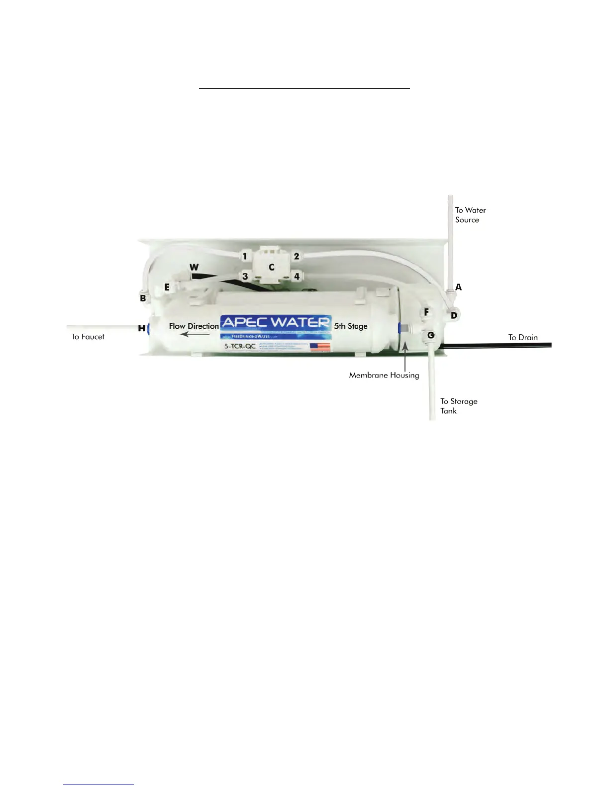
Non-Pumped RO HEAD DIAGRAM
RO Head Points Identication:
Point A: Feed water inlet into Stage-1 filter
Point B: Stage-3 filter’s output port
Point C
: Automatic-Shut-Off (ASO) valve. For Permeate Pumped systems, the permeate pump
replaces the ASO valve, it serves both as a pump and an auto-shut-off valve.
Point D
: Stage-4 Membrane housing inlet port. Feed water from Stage-3 filter enters the
Membrane at this port.
Point E: Check Valve. The filtered water from the Membrane passes through this Check Valve
before entering the storage tank. The Check Valve blocks the tank water from
back-flowing into the membrane.
Point F:
T-fitting on Stage-5 filter. This end of the T-fitting connects to the CLEAR pure water line.
Point G: T-fitting on the Stage-5 filter. This other end of the T-fitting connects to the YELLOW pure
water line which goes to the tank’s valve.
Point H
: The output end of Stage-5 filter. Pure water leaves Stage-5 filter via this port, and flows
onto the dispensing faucet.
Fig. 16
 Loading...