FOR MODELS: JGW, JGR AND JGJ SECTION 5 - MAINTENANCE
1/01 PAGE 5 - 23
under the piston as the piston is moved throughout its stroke. Re-measure vertical run out
and compare to acceptable limits in the table above. The horizontal readings, taken without
the use of feelers are to be used for acceptance. Copy Table 5-5 and record calculations
and readings.
If readings are not within acceptable limits after replacing worn parts and correcting any pip-
ing misalignment, the piston rod assembly should be replaced.
Piston Rings
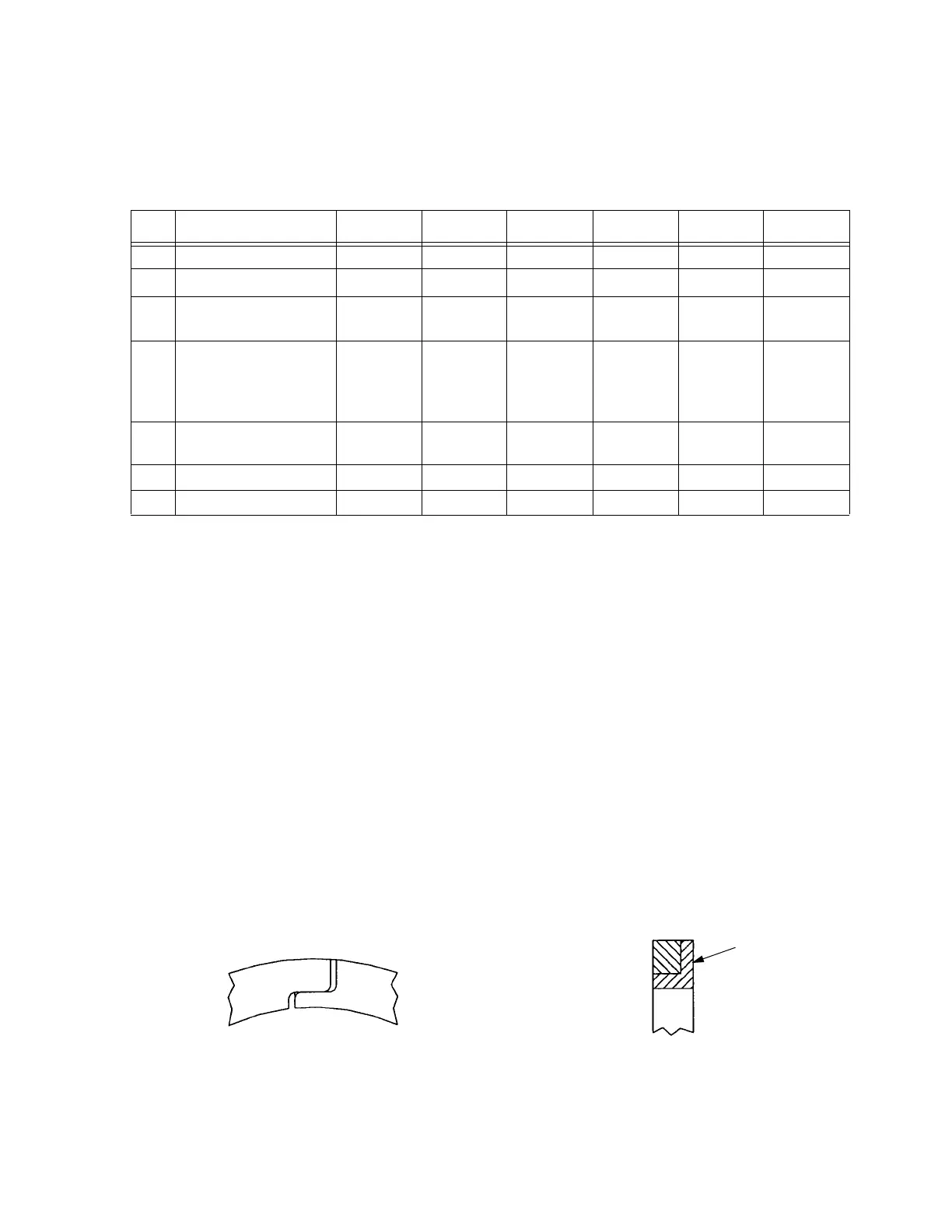
All JGW, JGR and JGJ cylinders use one-piece angle cut filled Teflon piston rings, excepting
tandem cylinders which use stepped seal-joint piston rings and very small cylinders which
use two-piece rings. Seal-joint rings are available for double acting cylinders. Refer to Figure
5-13:.
Seal-joint piston rings are directional and must be installed properly.
To utilize the seal-joint rings in double acting cylinders, in place of angle cut rings, contact
Ariel for new part numbers.
TABLE 5-5: FEELER THICKNESS TO CORRECT FOR PISTON WEIGHT
LINETHROW NUMBER:123456
1 Top Feeler Clearance
2
Line 1 (
)2)
3
JGJ
Line 2 - 0.003”
(-0.08 mm)
- 0.003”
(-0.08 mm)
- 0.003”
(-0.08 mm)
- 0.003”
(-0.08 mm)
- 0.003”
(-0.08 mm)
- 0.003”
(-0.08 mm)
- 0.003”
(-0.08 mm)
4
JGW
&
JGR
Line 2 - 0.004”
(-0.10 mm)
- 0.004”
(-0.10 mm)
- 0.004”
(-0.10 mm)
- 0.004”
(-0.10 mm)
- 0.004”
(-0.10 mm)
- 0.004”
(-0.10 mm)
- 0.004”
(-0.10 mm)
4 Bottom Feeler
Thickness
5Vertical~Piston @ CE000000
6 Vertical~Piston @ HE
FIGURE 5-13: SEAL-JOINT RINGS
Stamped Side
Toward Pressure
 Loading...