EasyManuals Logo

ASROCK X570 Steel Legend User Manual

ASROCK X570 Steel Legend
95 pages
To Next Page IconTo Next Page
To Previous Page IconTo Previous Page
Page #36 background imageLoading...
Page #36 background image
English
30
2.6 Onboard Headers and Connectors
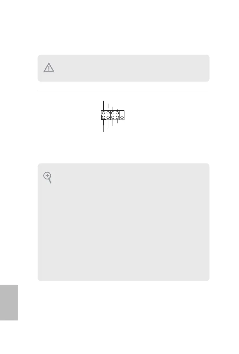
System Panel Header
(9-pin PANEL1)
(see p.8, No. 17)
Connect the power
button, reset button and
system status indicator on
the chassis to this header
according to the pin
assignments below. Note
the positive and negative
pins before connecting
the cables.
GND
R ESET#
PWRBTN#
PLED-
PLED+
GND
HDLED-
HDLED+
1
GND
Onboard headers and connectors are NOT jumpers. Do NOT place jumper caps over these
headers and connectors. Placing jumper caps over the headers and connectors will cause
permanent damage to the motherboard.
PWRBTN (Power Button):
Connect to the power button on the chassis front panel. You may congure the way to turn
o your system using the power button.
RESET (Reset Button):
Connect to the reset button on the chassis front panel. Press the reset button to restart the
computer if the computer freezes and fails to perform a normal restart.
PLED (System Power LED):
Connect to the power status indicator on the chassis front panel. e LED is on when the
system is operating. e LED keeps blinking when the system is in S1/S3 sleep state. e
LED is o when the system is in S4 sleep state or powered o (S5).
HDLED (Hard Drive Activity LED):
Connect to the hard drive activity LED on the chassis front panel. e LED is on when the
hard drive is reading or writing data.
e front panel design may dier by chassis. A front panel module mainly consists of power
button, reset button, power LED, hard drive activity LED, speaker and etc. When connect-
ing your chassis front panel module to this header, make sure the wire assignments and the
pin assignments are matched correctly.

Other manuals for ASROCK X570 Steel Legend

Questions and Answers:

Question and Answer IconNeed help?

Do you have a question about the ASROCK X570 Steel Legend and is the answer not in the manual?

ASROCK X570 Steel Legend Specifications

General IconGeneral
Processor socketSocket AM4
Processor manufacturerAMD
Compatible processor seriesAMD Ryzen 3 2nd Gen, AMD Ryzen 3 3rd Gen, AMD Ryzen 5 2nd Gen, AMD Ryzen 5 3rd Gen, AMD Ryzen 7 2nd Gen, AMD Ryzen 7 3rd Gen, AMD Ryzen 9 3rd Gen
Audio chipRealtek ALC1220
CertificationFCC, CE, ErP/EuP
Component forPC
Motherboard chipsetAMD X570
Audio output channels7.1 channels
Motherboard form factorATX
Windows operating systems supportedWindows 10 x64
ECCYes
Memory channelsDual-channel
Memory slots typeDIMM
Number of memory slots4
Supported memory typesDDR4-SDRAM
Maximum internal memory128 GB
Supported memory clock speeds2133, 2400, 2667, 2933, 3200, 3466, 3600, 4133, 4200, 4266, 4300, 4400 MHz
BIOS typeUEFI AMI
ACPI version5.1
BIOS memory size256 Mbit
System Management BIOS (SMBIOS) version2.3
DirectX version12.0
Maximum resolution4096 x 2160 pixels
Parallel processing technology support-
DisplayPort version1.2
PS/2 ports quantity1
USB 2.0 ports quantity0
USB 3.2 Gen 1 (3.1 Gen 1) Type-A ports quantity6
LAN controllerIntel® I211-AT
Ethernet interface typeGigabit Ethernet
Weight1500 g
Number of M.2 (M) slots2
Number of SATA III connectors8
Supported storage drive interfacesM.2, PCI Express 3.0, SATA III
Harmonized System (HS) code84733020
Weight and Dimensions IconWeight and Dimensions
Depth244 mm
Width305 mm
Height87 mm

Related product manuals