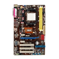
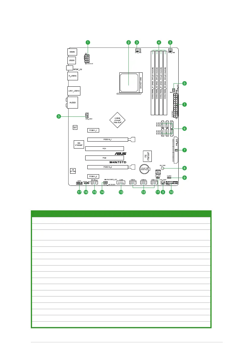
1.5.3 Motherboard layout
1.5.4 Layout contents
Connectors/Jumpers/Slots Page
1. ATX power connectors (24-pin EATXPWR, 8-pin EATX12V) 1-24
2. CPU socket AM3
1-6
3. CPU, Chassis and Power Fan connectors (4-pin CPU_FAN, 4-pin CHA_FAN1,
3-pin CHA_FAN2, 3-pin PWR_FAN)
1-26
4. DDR3 DIMM slots
1-9
5. MemOK! switch
1-18
6. Serial ATA connectors (7-pin SATA1-6)
1-25
7. IDE connector (40-1 pin PRI_IDE)
1-23
8. Standby power LED (SB_PWR)
1-19
9. Clear RTC RAM (CLRTC)
1-16
10. System panel connector (20-8 pin PANEL)
1-27
11. CPU overvoltage setting (3-1 pin OV_CPU)
1-17
12. USB connectors (10-1 pin USB78, USB910, USB1112)
1-28
13. Serial port connector (10-1 pin COM1)
1-29
14. Core Unlocker switch (CORE_UNLOCKER)
1-19
15. IEEE 1394a connector (10-1 pin IE1394_2)
1-30
16. Digital audio connector (4-1 pin SPDIF_OUT)
1-28
17. Front panel audio connector (10-1 pin AAFP)
1-29
Chapter 1: Product introduction 1-5
 Loading...