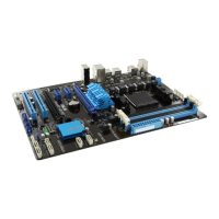
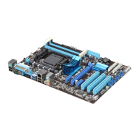
7. USB 2.0 ports 1 and 2. These two 4-pin Universal Serial Bus (USB) ports are for
USB 2.0/1.1 devices.
8. USB 3.0 ports 1 and 2
. These two 4-pin Universal Serial Bus (USB) ports are for USB
3.0 devices.
9. Serial port.
This 9-pin COM1 port is for pointing devices or other serial devices.
10. USB 2.0 ports 3 and 4.
These two 4-pin Universal Serial Bus (USB) ports are for
USB 2.0/1.1 devices.
Audio 2, 4, 6, or 8-channel conguration
Port Headset 2-channel 4-channel 6-channel 8-channel
Light Blue (Rear panel) Line In Rear Speaker Out Rear Speaker Out Rear Speaker Out
Lime (Rear panel) Line Out Front Speaker Out Front Speaker Out Front Speaker Out
Pink (Rear panel) Mic In Mic In Bass/Center Bass/Center
Lime (Front panel) – – – Side Speaker Out
To congure an 8-channel audio output:
Use the chassis with HD audio module in the front panel to support 8-channel audio output.
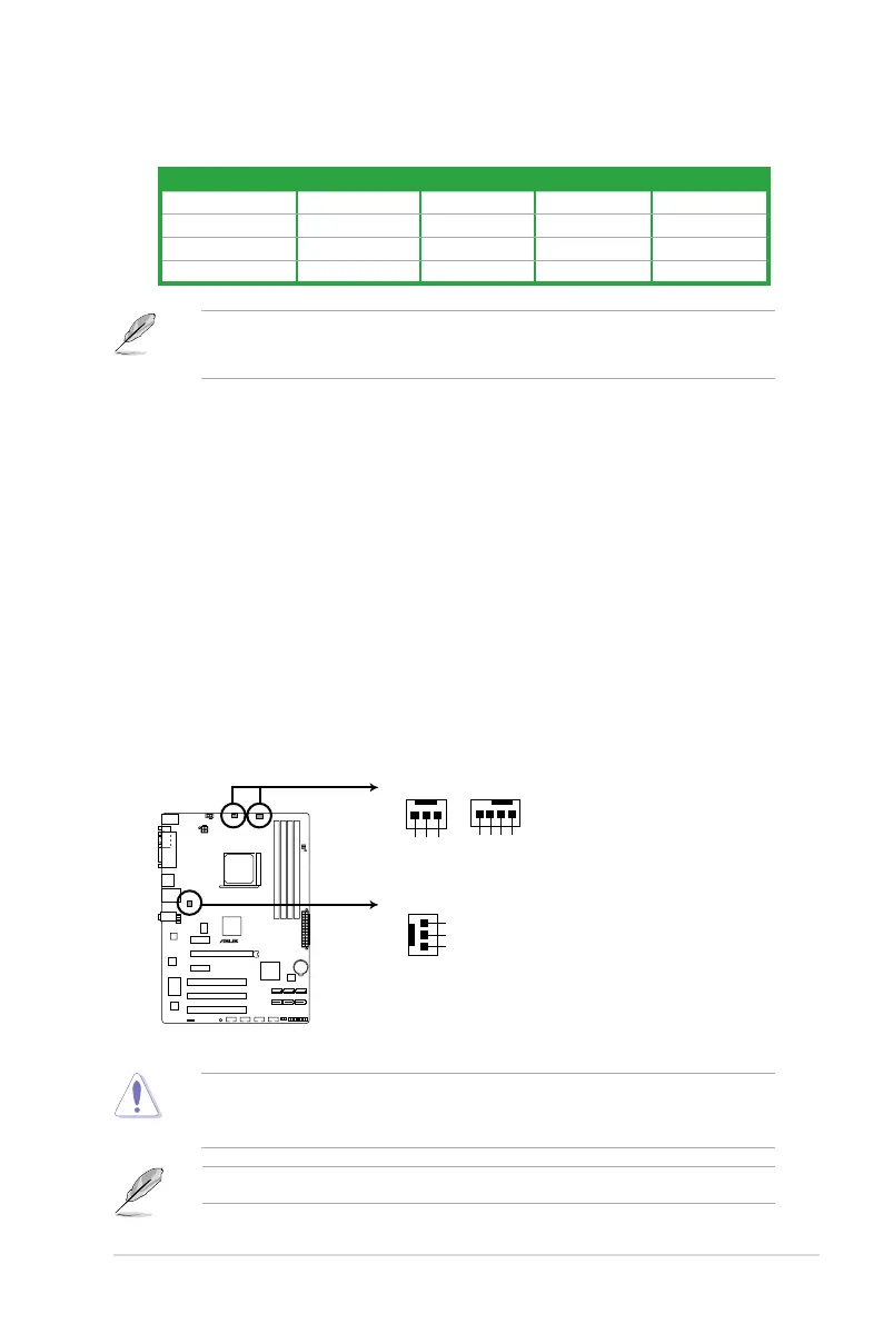
1.10.2 Internal connectors
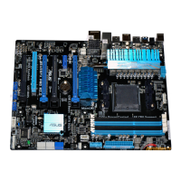
1. Power, CPU and chassis fan connectors (3-pin PWR FAN, 4-pin CPU_FAN and
3-pin CHA_FAN)
Connect the fan cables to the fan connectors on the motherboard, ensuring that the
black wire of each cable matches the ground pin of the connector.
Only the 4-pin CPU fan supports the ASUS Q-Fan feature.
DO NOT forget to connect the fan cables to the fan connectors. Insufcient air ow inside
the system may damage the motherboard components. These are not jumpers! DO NOT
place jumper caps on the fan connectors.
M5A87 Fan connectors
Rotation
+12V
GND
PWR_FAN
GND
+12V
Rotation
CHA_FAN
CPU_FAN
CPU FAN PWM
CPU FAN IN
CPU FAN PWR
GND
M5A87
ASUS M5A87 1-21
 Loading...