1-4 Chapter 1: Product Introduction
6. Power Indicator
• The color definition of the power indicator is as the below table.
Status Description
Blue ON
Amber Standbymode
OFF OFF
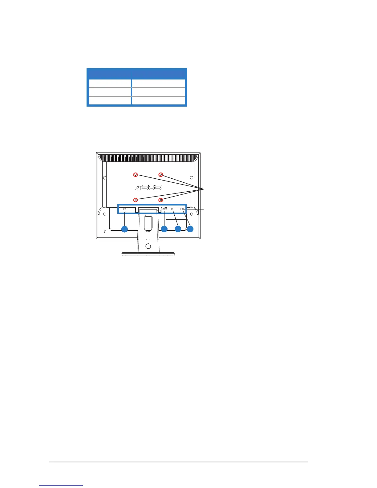
1.4.2 Rear of the LED monitor
4
3
2
1
Screw holes for
VESAWallMount
Rear connectors
Rear connectors (from left to right)
1. AC-IN port. This port connects the power connector from the bundled power
cord.
2. Audio-in port.ThisportconnectsPCaudiosourcebythebundledaudio
cable.(VB178T/S,VB198T/S)
3. DVI port.This24-pinportisforPC(PersonalComputer)DVI-Ddigitalsignal
connection.(VB178T/N,VB198T/N)
4. D-SUB port.This15-pinportisforPCVGAconnection.
 Loading...