ATI Q46 Modbus Communications Manual
8
O&M Manual
Rev-D (2/16)
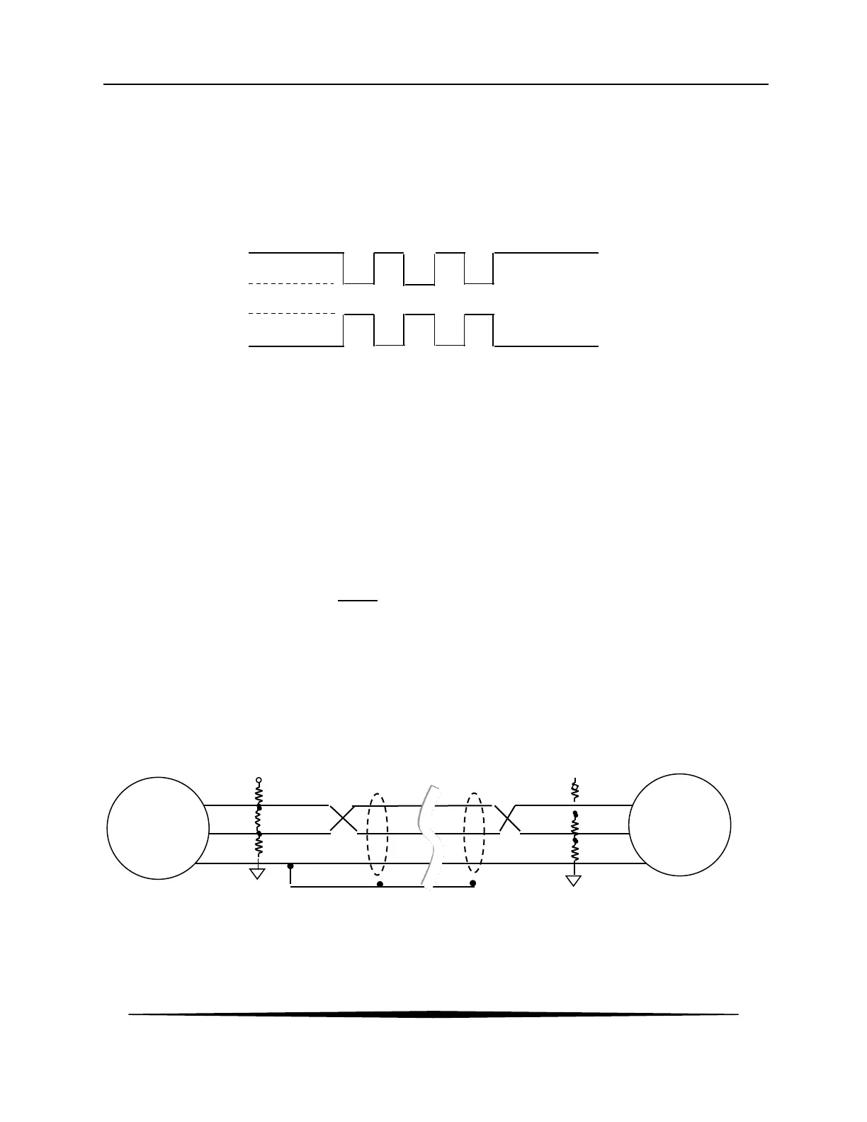
1.6 RS-485 Line Drivers/Receivers
The differential lines, A and B, may be operated at TTL levels of 0 and 5 volts. The RS485 line
driver outputs the logic high state (marking, or idle state) by driving 5 volts on B, and 0 volts on A.
Conversely, the driver outputs the logic low state (spacing) by driving 5 volts on A, and 0 volts on
B.
Over a distance of 4000 feet, the 5 volts applied to either line may be dropped significantly. This
usually doesn’t present a problem since RS485 receivers are specified to operate with a
differential voltage of only 0.200 volts. In practice, however, the differential voltage should remain
above 1.5v.
Logic State High (Idle or Marking State): (B – A) >= 200mV
LogicState Low (SpacingState): (A – B) >= 200mV
1.7 120 Ohm Termination
The two devices at the furthest end of the bus require termination resistors to cancel reflections.
Intermediate devices do not. The Q46 has a selectable termination resistor on the Modbus card
just behind the terminal strip. ONLY set to “ON” position if the Q46 is an End-of-Bus unit.
1.8 Bias
When there is no communication on the network, the A and B lines are floating. A small amount
of noise could appear as the start of a message, which might interfere with the framing of valid
messages. Biasing the transmission line keeps it in the idle state while it is not driven. The bias
resistors maintain a differential of 200mV between the A and B lines. Note that bias resistors are
not required for Q46 Series transmitters, as the Modbus driver includes a “Failsafe” built-in Bias
Design.
A(-)
B(+)
 Loading...