2920 1462 00
13
Instruction book
1.3.3 Display
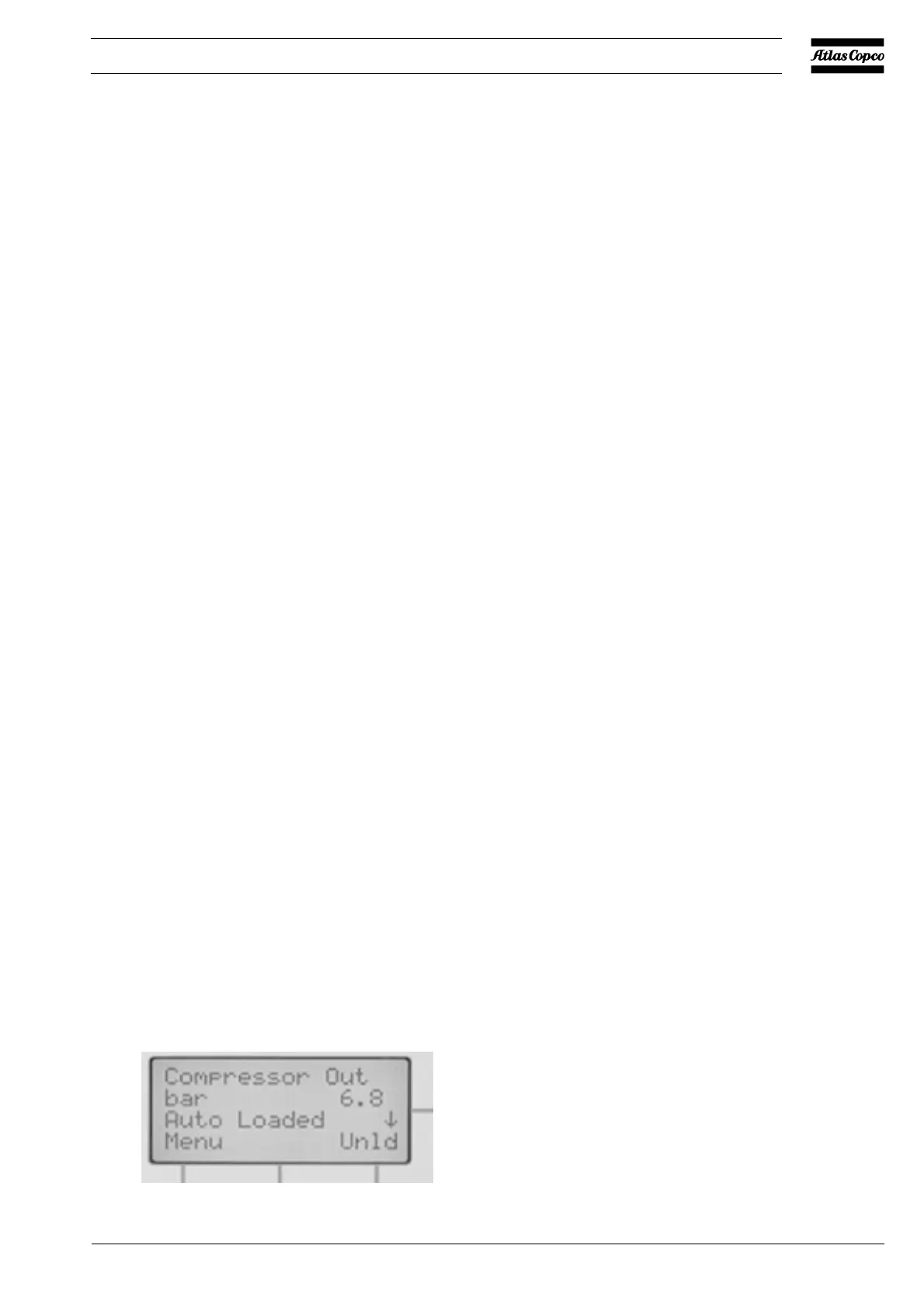
Normally, the display shows the operation status of the
compressor, the air outlet pressure and the abbreviations of
function keys F1, F2 and F3.
1.3.4 Calling up other menus
Starting from the Main display (Fig. 1.12):
- Use the ¯ key (4-Fig. 1.9) for a quick look at the actual
compressor status
- Press the key Menu (F1), the option "Status data" will be
followed by a horizontal arrow:
- either press the tabulator key (5-Fig. 1.9) to select this
menu
- or use the ¯ key to scroll until the desired submenu is
followed by a horizontal arrow and then press the
tabulator key (5) to select this menu.
For detailed instructions, consult the User manual for
Elektronikon I and II regulators.
Fig. 1.12 Example of the main display
SENSORS/SOLENOID VALVES/
ELECTRONIC DRAIN
PT20 Pressure sensor, air outlet
TT11 Temperature sensor,
compressor element outlet
TT90 Temperature sensor,
dewpoint (Full-Feature)
Y1 Loading solenoid valve
MOTORS
M1 Drive motor
M2 Fan motor, compressor
coolers (air-cooled
compressors)
ELECTRIC CABINET
F1/F11 Fuses
F21 Overload relay, drive motor
K11 Auxiliary contactor for dryer
(Full-Feature)
K21 Line contactor
K22 Star contactor
K23 Delta contactor
K25 Phase sequence protection
Q15 Circuit breaker
T1/T2 Transformers
T3 Transformer, dryer
1X0/1X8 Terminal strips
CONTROL MODULE (E1)
I Start button
K01 Blocking relay
K02 Auxiliary relay, star
contactor
K03 Auxiliary relay, delta
contactor
K04 Auxiliary relay, loading/
unloading
K05 Auxiliary relay, air pressure
high/low
K06 Auxiliary relay, dryer
K07 Auxiliary relay, manual/
automatic operation
K08 Auxiliary relay, warning
K09 Auxiliary relay, shut-down
O Stop button
S3 Emergency stop button
DRYER
A1 Dryer (Full-Feature)
OPTIONAL EQUIPMENT
AIE1 Expansion module, analog
input
B1 Electronic water drain (EWD)
PDS11 DP switch for DD filter
R1/K34 Drive motor thermistor
protection, shut-down
R2/K35 Drive motor thermistor
protection, warning
R3/R4 Heaters, freeze protection
R5 Heater, electronic water drain
R7 Heater, cubicle
R96/97 Anti-condensation heaters
S10 Main power isolating switch
TSLL91 Thermostat, cubicle freeze
protection
TT51/52 Temperature sensors, energy
recovery
Y2 Solenoid valve, modulating
control
Fig. 1.11 Electrical diagram, GA Workplace / Workplace FF - 50 Hz with star-delta starter (typical example)
52158F
 Loading...