2920 1462 00
25
Instruction book
3.5 Before starting
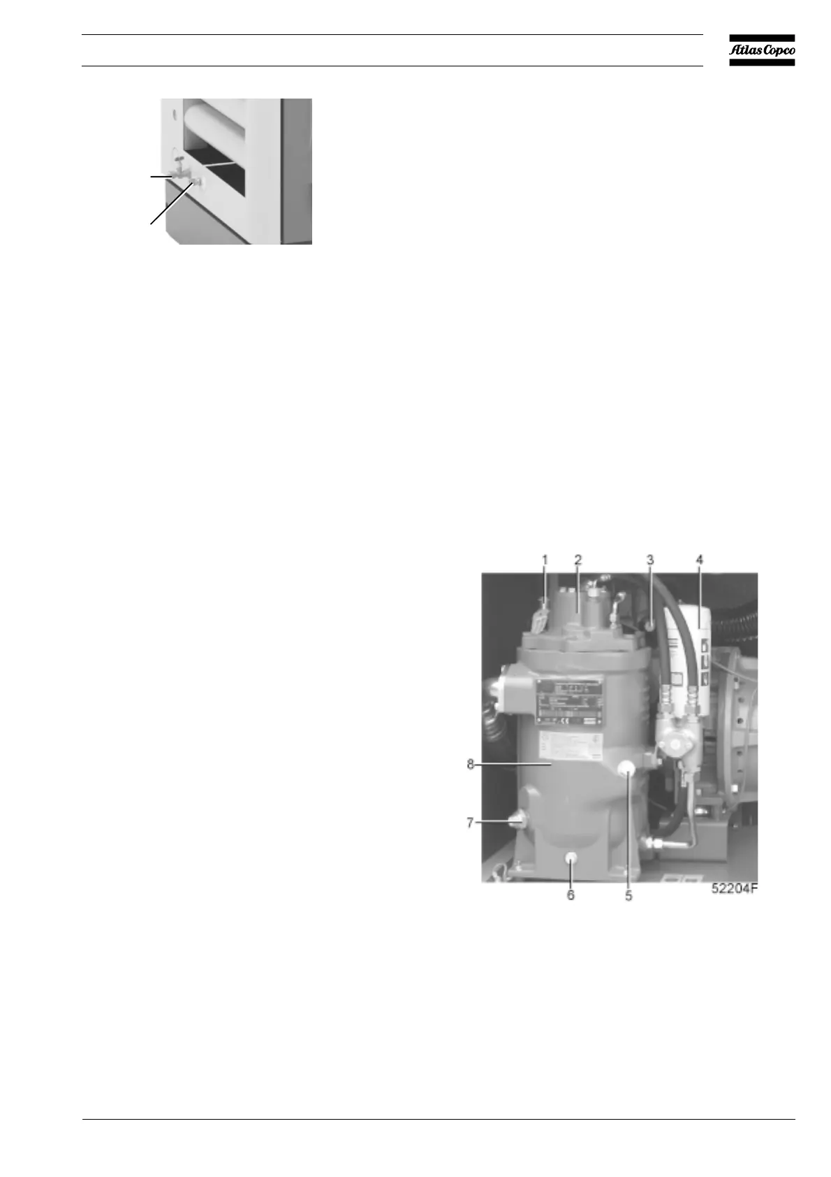
1. Check the oil level (7-Fig. 3.3). The pointer should register
in the upper field of the green range or above it.
2. If the red part of service indicator (3-Fig. 3.3) shows full
out, replace air filter element (1-Fig. 5.1). Reset the service
indicator by pushing the knob in the extremity of the body
and reset the service warning (see the User manual for the
Elektronikon regulator).
3.6 Operating GA Workplace/Workplace FF
GA Workplace and Workplace FF are provided with the
Elektronikon II regulator (Fig. 3.5).
3.6.1 Starting
1. Switch on the voltage. Check that voltage on LED (6-Fig.
3.5) lights up.
2. Open air outlet valve (1-Fig. 3.4).
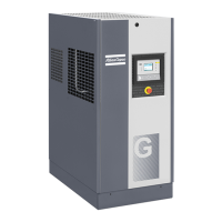
3. Close condensate drain valve (1-Fig. 3.2).
4. Press start button (2-Fig. 3.5). The compressor starts
running and automatic operation LED (8) lights up. Ten
seconds (programmable) after starting, the drive motor
switches over from star to delta. At the same time
(programmable), the compressor starts running loaded. The
message on display (3) changes from "Auto unloaded" to
"Auto loaded".
1 Condensate drain valve
2 Automatic condensate drain
Fig. 3.2 Condensate outlets
3.6.2 During operation
1. Check the oil level during loaded operation: the pointer
of level gauge (7-Fig. 3.3) must register in the green range.
2. When automatic operation LED (8-Fig. 3.5) is alight, the
regulator is automatically controlling the compressor, i.e.
loading, unloading, stopping of the motors and restarting.
3.6.3 Checking the display
1. Regularly check display (3-Fig. 3.5) for readings and
messages. Normally, the display shows the compressor
outlet pressure, the status of the compressor and the
abbreviations of the functions of the keys below the display.
2. Always check display (3-Fig. 3.5) and remedy the trouble
if alarm LED (7) is alight or blinks. Consult the User manual
for Elektronikon I and II regulators, Part 2, sections 5 and
15.
1 Safety valve
2 Minimum pressure valve
3 Service indicator, air filter
4 Oil filter
5 Oil filler plug
6 Oil drain plug
7 Oil level gauge
8 Air receiver/oil separator
Fig. 3.3 Oil system components and transport fixations
51100F
1
2
 Loading...