2920 1462 00
3
Instruction book
1 Leading particulars
1.1 General description
GA11 up to GA30C are stationary, single-stage, oil-injected
screw compressors driven by an electric motor. The
compressors are air-cooled.
1.1.1 Compressor variants
GA Pack
GA Pack are enclosed in a sound-insulated bodywork. The
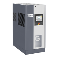
compressors are controlled by the Atlas Copco Elektronikon
®
I regulator (Fig. 1.1). The electronic control module is fitted
to the door at the front side. An electric cabinet comprising the
motor starter is located behind this panel.
GA Pack FF
GA Pack FF (Full-Feature) are also controlled by the Atlas
Copco Elektronikon
®
I regulator (Fig. 1.1). They are
additionally provided with an air dryer integrated in the sound-
insulated bodywork. The dryer removes condensate from the
compressed air by cooling the air to near freezing point and
automatically draining the condensate. See section 1.5.
GA Workplace
GA Workplace are enclosed in a sound-insulated bodywork.
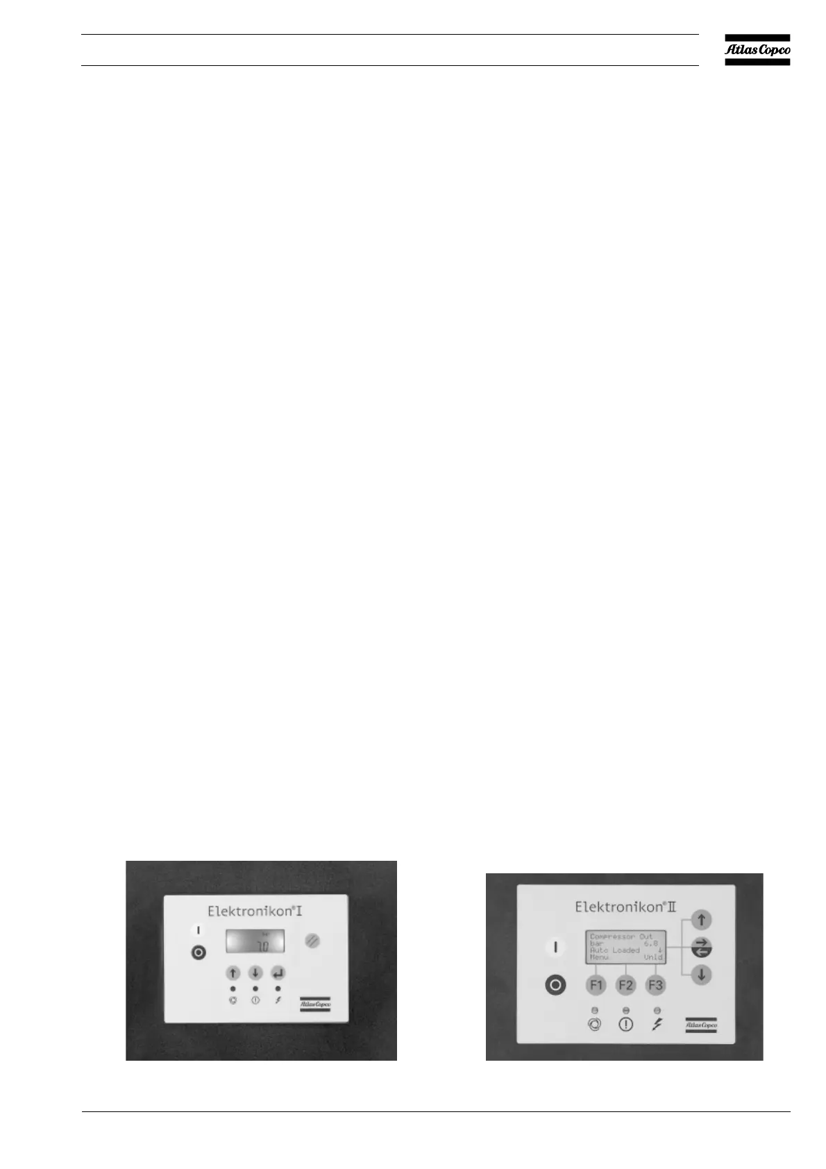
The compressors are controlled by the Atlas Copco
Elektronikon
®
II regulator (Fig. 1.2). The electronic control
module is fitted to the door at the front side. An electric cabinet
comprising the motor starter is located behind this panel. A
condensate trap with automatic drain system is provided.
GA Workplace FF
GA Workplace FF (Full-Feature) are also controlled by the Atlas
Copco Elektronikon
®
II regulator (Fig. 1.2). They are
additionally provided with an air dryer integrated in the sound-
insulated bodywork. The dryer removes condensate from the
compressed air by cooling the air to near freezing point and
automatically draining the condensate. See section 1.5.
1.1.2 Air flow (Figs. 1.7 and 1.8)
Air drawn through filter (1) and open inlet valve (6) into
compressor element (5) is compressed. Compressed air and
oil flow through air receiver/oil separator (15) and air cooler
(10) to outlet valve (21).
Minimum pressure valve (12) prevents the receiver pressure
from dropping below a minimum pressure.
1.1.3 Oil system (Figs. 1.7 and 1.8)
Air pressure forces the oil from air receiver (15) through oil
cooler (11) and filter (18) to compressor element (5) and the
lubrication points.
The system comprises a by-pass valve (20). When the oil is
warm, the valve allows all oil to pass through the cooler.
1.1.4 Cooling system (Figs. 1.7 and 1.8)
The cooling system comprises air cooler (10) and oil cooler
(11). The cooling air is generated by fan (9).
Fig. 1.1 Elektronikon I regulator
Fig. 1.2 Elektronikon II regulator
52144F
52143F
 Loading...