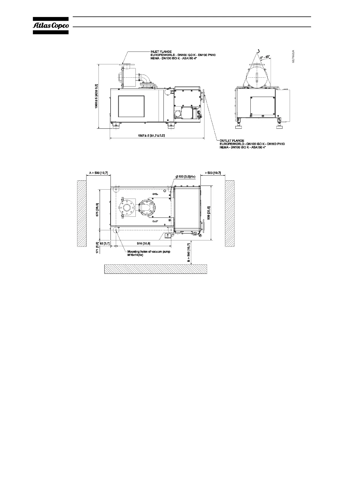
Figure 37 Installation proposal - GVS 630A
A. Space for access to electrical
connection
B. Space for exhaust filter exchange
and cooling air flow
A. Space for access to electrical
connection
B. Space for exhaust filter exchange
and cooling air flow
5.2. Installation guidelines
The following list must be used as a guide for the installation of GVS vacuum
pumps. The list is not exhaustive. Every vacuum pump installation is unique and
care must be exercised in the placement of each pump. If you are unsure of any
installation variable, please consult us.
▪ Install the pump on a solid, level surface, suitable for taking its weight.
Respect the minimal distance between the pump and the walls (Refer to
Dimension drawings on page 24).
▪ Correct process lines sizes have to be used to prevent restrictions and
resulting pressure drops. As a rule of thumb, the inlet diameter of the pump
should be maintained as far into the process as possible. Consult us for piping
recommendations.
▪ The required ventilation capacity to limit the vacuum pump room temperature
can be calculated from Qv = 0.2 N/Δt, with
Qv = required ventilation capacity in m
3
/s
12/2021 - ©Atlas CopcoPage 556996022430_C
Installation
 Loading...