Instruction book
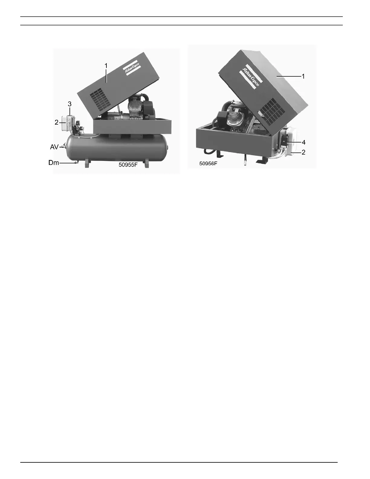
Fig. 1.13 Optional silencing hood
Fig. 1.14 Pack compressor with optional silencing
hood
AV Air outlet valve
Dm Condensate drain valve
1 Silencing hood (standard option)
2 Electric cabinet
3 On/off switch
4 Air pressure switch with on/off switches
Figs. 1.13 and 1.14 Pack - silencing hood
1.3.3 LE/LF/LT Trolley (Fig. 1.12)
The regulating system includes:
- Pilot valve (RV)
- Unloader (UA) with integrated check valve (CV)
- Electric cabinet (11) (only on electric motor driven Trolley compressors)
Operation
Pilot valve (RV) opens and closes at pre-set pressures. During loaded operation, pilot valve (RV) is
closed preventing the compressed air from flowing to unloader (UA).
When the pressure in the pulsation dampers (PD) reaches the pre-set maximum pressure, pilot valve (RV)
will open. Compressed air from the pulsation dampers will flow to plunger (12) which causes unloading
valve (UV) to open. The air at the delivery side of the compressor is blown through silencer (9) to
atmosphere and check valve (CV) closes to prevent venting of the pulsation dampers. The compressor
runs unloaded.
When the pressure in the pulsation dampers decreases to the pre-set minimum pressure, the pilot valve
closes. Control air from the unloader plunger chamber is vented to atmosphere. Unloading valve (UV)
closes and compressed air is supplied to the pulsation dampers again.
2920 1585 00 - 13 -
 Loading...