Instruction Manual
2954 9020 00 11
2.6 Remote start (RS)
"Remote start" allows to switch the unit on or off without using the
control panel located on the unit. The start module of the control
panel provides extra connections for the remote start/stop switch
and the plant contactor (voltage free contact), both to be installed
by the customer.
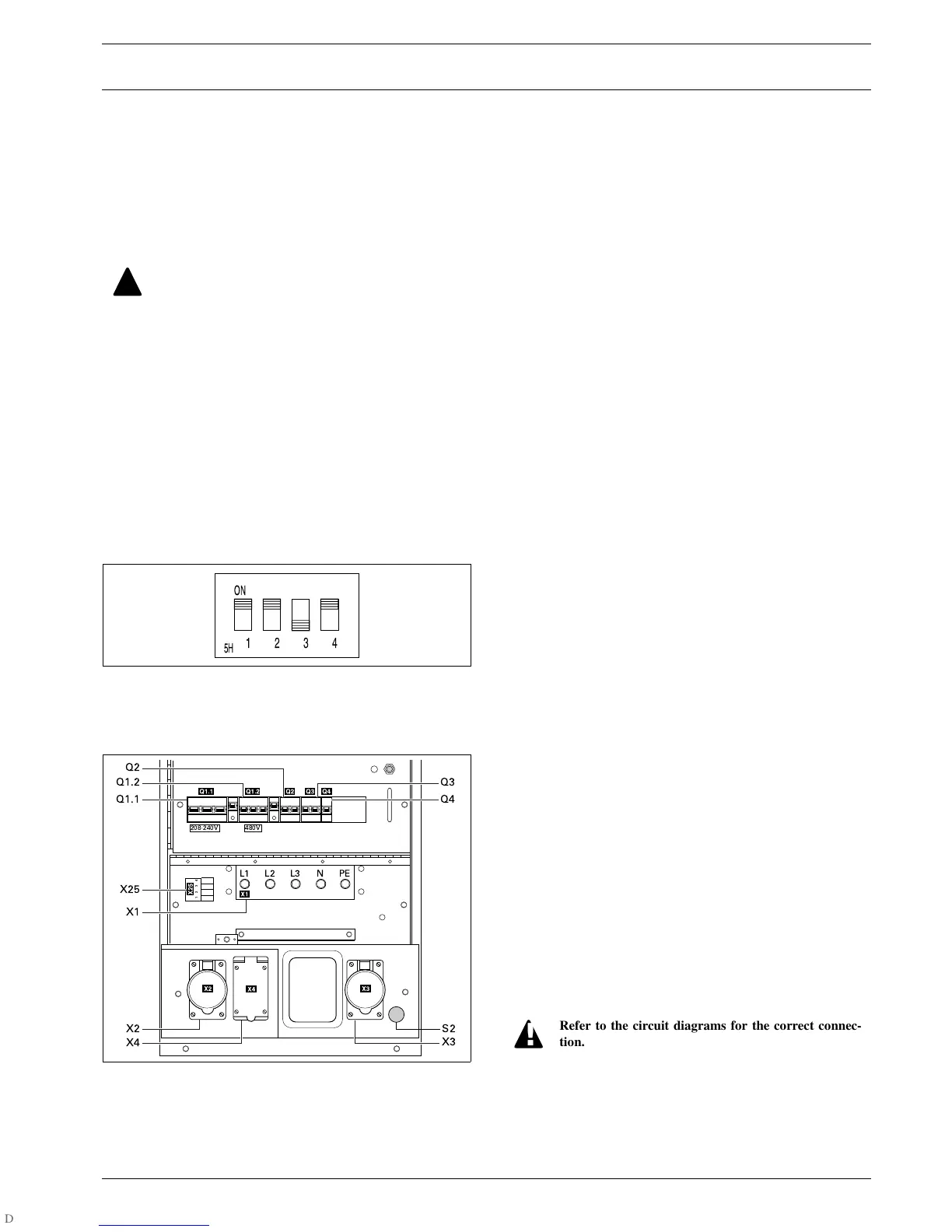
2.7 Dip-switches
For correct functioning of the module, the DIP switches at the back
of the control module should be positioned as follows:
2.8 Output connections
The output connections are situated below the control and indicator
panel.
S2 ......Emergency stop button
Push the button to stop the generator in case of an emergency.
When the button is pressed, it must be unlocked, by turning it
anti-clockwise, before the generator can be restarted.
Q1.1...Circuit breaker for low voltage
Interrupts the low voltage power supply towards X1, X2, X3
and X4 when a short-circuit occurs at the load side, or when the
overcurrent protection (125 A) is activated. It must be reset
manually after eliminating the problem.
Q1.2...Circuit breaker for high voltage
Interrupts the high voltage power supply towards X1, X2, X3
and X4 when a short-circuit occurs at the load side, or when the
overcurrent protection (50 A) is activated. It must be reset man-
ually after eliminating the problem.
Q2......Circuit breaker
Interrupts phases L1 and L2 towards X2 when a short-circuit
occurs at the load side, or when the overcurrent protection
(50 A) is activated. It must be reset manually after eliminating
the problem.
Q3......Circuit breaker
Interrupts line L1 and L2 towards X3 when a short-circuit oc-
curs at the load side, or when the overcurrent protection (50 A)
is activated. It must be reset manually after eliminating the
problem.
Q4......Circuit breaker
Interrupts line L2 towards X4 when a short-circuit occurs at the
load side, or when the overcurrent protection (20 A) is activat-
ed. It must be reset manually after eliminating the problem.
X1......Main power supply - Terminal board
Terminals L1, L2, L3, N (=neutral) and PE (=grounding), hid-
den behind the control panel door and behind a small transpar-
ent door.
X2......Single phase outlet socket
Provides lines L1, L2, and N (=neutral).
X3......Single phase outlet socket
Provides lines L1, L2, and N (=neutral).
X4......Single phase outlet socket
Provides lines L2, N (=neutral) and PE (=grounding).
X25....Connection block
Allows easy connection for a remote start switch.
The plant contactor should be sized according to the
load. The maximum current through the voltage
free contact is 3 A.
The remote start/stop switch Sx has to meet the fol-
lowing specifications: 12 V DC, 4 A.
Refer to the circuit diagram for the correct connec-
tion of the plant contactor and the remote start/stop
switch.
A shunt trip coil will switch off Q1.1 or Q1.2
(depending on the mode the unit is running in) in
case of an emergency stop or an earth fault.
 Loading...


