Mediant 1000 Analog & Digital
Fast Track Guide 10 Document #: LTRT-83501
2.4 Cabling the Mediant 1000
Protective Earthing
The equipment is classified as Class I EN60950 and UL60950 and must be earthed at all
times. Units providing power sockets with three pins must be connected by service
personnel to a socket-outlet with a protective earthing connection.
¾ To cable the Mediant 1000, take these 8 steps:
1. The Mediant 1000 must be permanently earthed using an equipment-earthing conductor.
Connect an electrically earthed strap of 16 AWG wire (minimum) to the chassis earthing
screw, using the supplied washer. The connection to the protective earthing must be in
accordance with the regulations enforced in the country of installation.
2. For Mediant 1000 digital interfaces: Connect the E1/T1 trunk cables to the RJ-48c ports
on the I/O module(s). Connect the other ends of the trunk cables to your PBX/PSTN switch.
For a 1+1 or 2+2 fallback option, connect trunks 1 and 3 to your PBX, and trunks 2 and 4 to
the PSTN. If the power fails, a relay connects trunks 1 to 2 and 3 to 4 (in the same module),
acting as a fallback for PSTN trunks. RJ-48c trunk connectors are wired according to Figure
2-1 below.
To protect against electrical shock and fire, use a 26 AWG min wire to connect T1 or E1
ports to the PSTN.
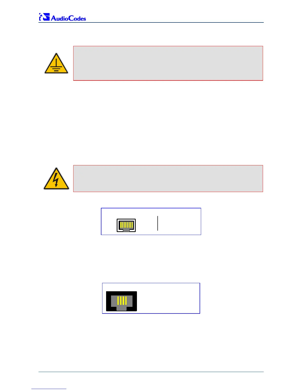
Figure 2-1: RJ-48c Trunk Connector Pinouts
1 2 3 4 5 6 7 8
3, 6, 7, 8
not connected
body = shield
1 = Rx RING
2 = Rx TIP
4 = Tx RING
5 = Tx TIP
RJ-48c Connector and Pinout
3. For Mediant 1000 analog interfaces (applicable only to SIP and H.323): Connect the
RJ-11 connectors of the analog FXS module/s to fax machines, modems, or telephones.
Connect the RJ-11 connectors of the analog FXO module/s to telephone exchange analog
lines or PBX extensions. Ensure that FXS and FXO are connected to the correct external
devices, otherwise damage can occur.
Figure 2-2: RJ-11 Telephone Connector Pinouts
1 2 3 4
1 Not connected
4 Not connected
2 Tip
3 Ring
 Loading...