Automatic Systems TR491-TR6-GB-a YD-JMW 20/01/00 Installation TR491 2-1106GB Rev.: C p. 10/12
AS1026 board
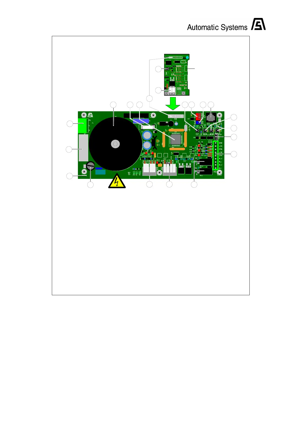
6. I2C expansion connector
20. Dropping arm test button
21. Dropping arm connector
Fig. 5
5:1
5:4
5:3
5:5
5:16
5:6
5:17 5:7 5:8 5:9
5:18
5:10
5:11
5:12
5:2
5:14
5:15
5:13
AS1025R2
5:19
1026R2
C1
C2
C3
C4
C5
C6
D2
D3
EMI1
EMI2
EMI3
EMI4
EMI5
EMI6
EMI7
EMI8
IC1
IC2IC3
LD1
LD2
LD3
LD4
LD5
LD6
LD7
PL1
PL2
Q1
Q2
Q3
Q4
Q5
Q6
Q7
Q8
Q9
Q10
Q11
R1R2
R3 R4
R5
R6R7
R8
R9
R10
R11
R12
R13
R14
R15
R16
R17
R18
R19
R20
R21
R22
R23
R24
R25
R26
R27 R28
R29
R30R31 R32
R33
R34
R35
R36
R37
SW1
X1
1
X2
X4
X5
X6
X7
AS
5:20
5:21
AS1026R2 board
TR6 CONTROL LOGIC
AS1025 board
1. 230V main power supply connector
2. Fuse 1: T500mAL 250V (230V power supply)
3. 60VA multivoltage transformer
4. AS1025 board
5. Fuse 2: T2AL 250V (24VDC voltage)
6. I2C expansion connector
7. Parameter programming DIP switches
8. DIP switches for selecting operation mode
and programming parameters
9. "AS-LINK" connector for programming console
10. Programming push button and LED
11. RS232 line TTL 5V level
12. Customer input/output connector
13. Signal relay
14. Direction A and B limit switches connector
15. Direction A and B electromagnets connector
16. Application microcontroller
17. Microcontroller reset button
18. Direction A and B simulation buttons
19. 230V power supply filter

 Loading...