Automatic Systems TR491-TR6-GB-a YD-JMW 20/01/00 Installation TR491 2-1106GB Rev.: C p. 4/12
2. GENERAL
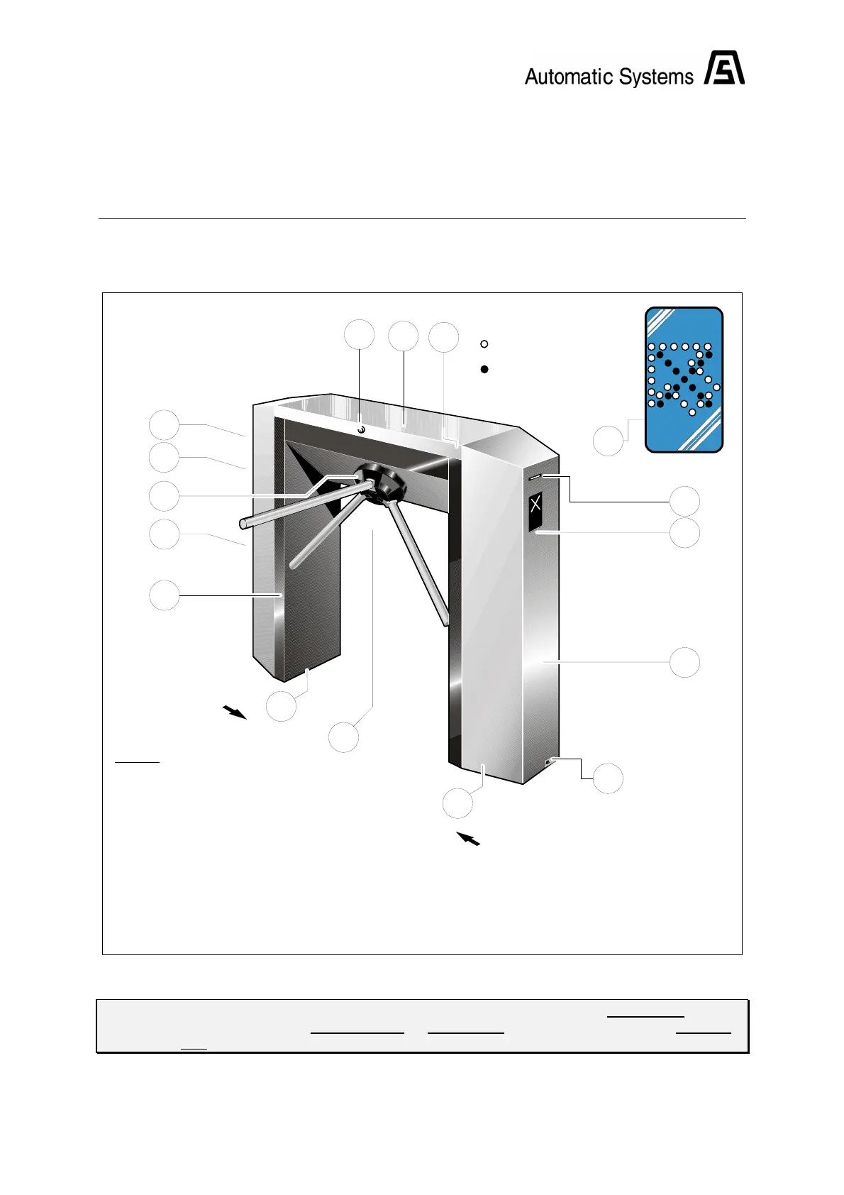
2.1. General view
Fig. 1
A
1:2
1:1 Front end section ("A") (hinged)
1:2 Rear end section ("B") (hinged)
Legend:
1:1
B
1:3
1:7
1:5
1:6 Tripod obstacle with stainless steel arms
1:7 Tripod turnstile mechanism (See Field manual)
1:4 Approach pictogram (option)
1:5 Card reader (option)
1:8 Electrical control logic
1:9 Floor fixing
1:5
1:8
1:10
1:4
1:3 Hood
1:10 Steel housing
1:4
1:11 Commercial identification plate
Green arrow:
"PASSAGE IN SERVICE"
Approach
pictogram (option)
Red cross:
"PASSAGE OUT OF SERVICE"
1:6
1:4
1:9
1:9
1:11
1:12 Lock
1:12
Note: Conventionally and as a general rule, the user will be considered in direction "A" when
the turnstile is at his right-hand side, in direction "B" when the turnstile is at his left-hand
side.

 Loading...