J-58
Power
The inner circuit voltage starts to rise up for the fi rst 100ms
after power on, the input may not work at this time. And
also the inner circuit voltage drops down for the last 500ms
after power off, the input may not work at this time.
Reset input
*
*
T
1
Ta Tb
3×Ta
1
**
** **
Proper usage
Ta(ON width) and
Tb(OFF width) needed to be
over min.signal width.
Max. counting speed is 1/2
value of rated spec. when
duty ratio is 1:3.
It can not respond if it is smaller
than min. singal width(Ta).
(INHIBIT)
SW1
CP1 CP2 +12V 0V
INHIBIT
*Setting value
Time display value
0
(UP mode)
ENC-1-2-T-24
Please put black dot. Please put black dot.
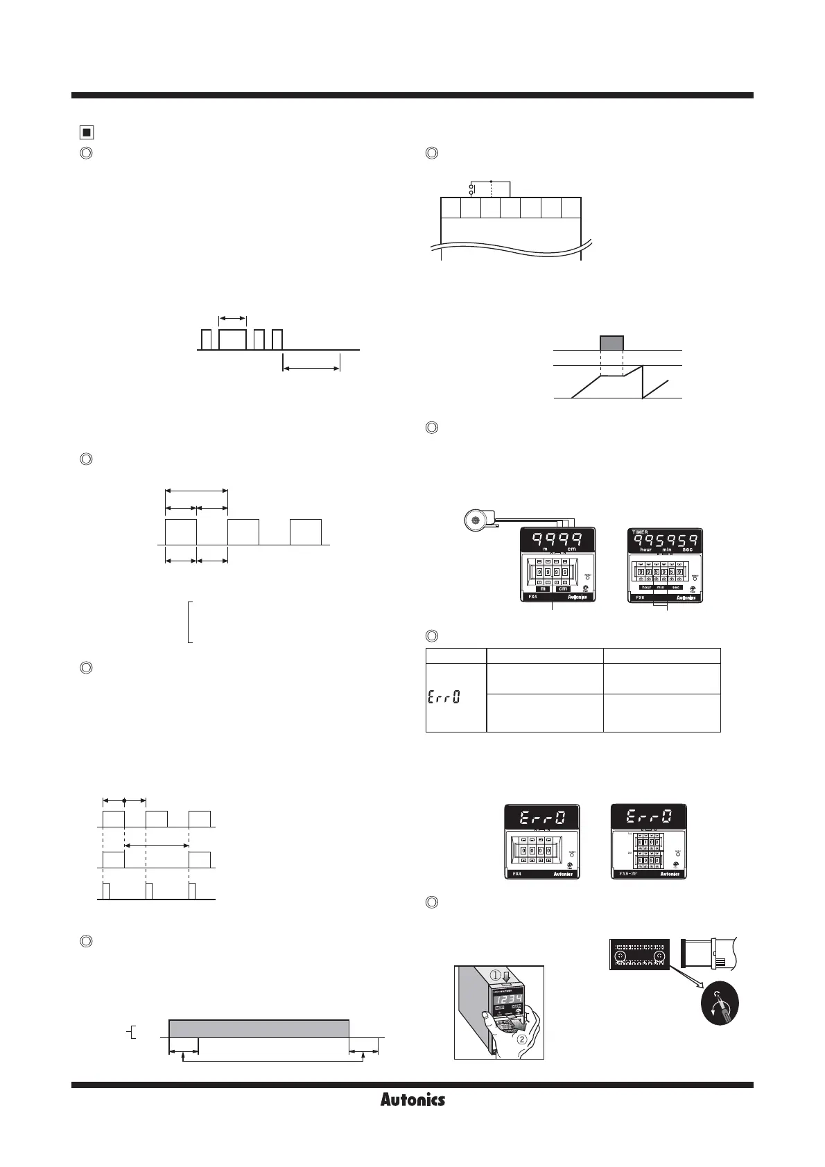
Ex1)Measurement of length by
the rotary encoder
EX2)Timer[F mode]
※1 ※2
8 9 10 11 12 13 14
※
1. Connection for PNP
2. Connection for NPN
FX4
*
In case of a contact reset, contact chattering will not
affect the reset as long as it is applied for a minimum of 20ms.
**
Input signal at CP1 & CP2 must be applied for a minimum
of 50ms after the reset is removed.
*
Please make duty ratio(ON/OFF) as 1:1.
**
Min. signal width
1cps : Min. 500ms
30cps : Min. 16.7ms
2kcps : Min. 0.25ms
5kcps : Min. 0.1ms
Power
ON
OFF
100
㎳
500
㎳
The unstable time
against the input signal
※
Please be careful of the injury caused by tools.
Unscrew the rear
bolt, and pull the
body backward.
①
Push down the front guide.
②
Pull out the front guide.
● FXL Series
Reset
● Reset
In case of changing the input mode after supplying the
power, please provide an external reset or manual reset.
If reset is not executed, the counter will be working in
previous mode.
● Reset signal width
To guarantee proper reset, the signal must be supplied for
a minimum of min. 20ms regardless the signal comes from
a contact or a solid-state input.
Mini. count signal width
Max. counting speed
This is a response speed per 1 sec. when the duty ratio
(ON:OFF) of input signal is 1:1. If the duty ratio is not
1:1, the width between ON and OFF should be over min.
signal width and the response speed will getting slower
against input signal. If either ON or OFF signal is shorter
than minimum signal width, this product may not respond.
INHIBIT(For timer)
● INHIBIT mode is active when SW1 turns ON. (Time Hold)
●
When power is applied, it starts to progress and INHIBIT mode
is used to stop the time is under the progress at the moment.
● When SW1 is OFF, timer starts to progress again.
How to use the sticker
The below sticker can be found inside the box.
Use the sticker according to application as follow;
Error display
Error signal Error description Returning method
When 2nd setting
value is 0
Change the setting
value to non zero status
When 2nd setting
value is smaller than
1st setting value
Make 2nd setting value
bigger than 1st setting
value
※
There is no Error display function in indication type.
※
There is no Error function in indicator.
※
When Error is display, the OUTPUT continues OFF state.
※
1st output maintains OFF status by 1st setting value as 0.
Case & DIP switch detachment
● FXH Series
FX/FXH/FXL Series
 Loading...