J-53
(A)
Photo
electric
sensor
(B)
Fiber
optic
sensor
(C)
Door/Area
sensor
(D)
Proximity
sensor
(E)
Pressure
sensor
(F)
Rotary
encoder
(G)
Connector/
Socket
(H)
Temp.
controller
(I)
SSR/
Power
controller
(J)
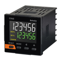
Counter
(K)
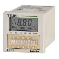
Timer
(L)
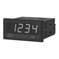
Panel
meter
(M)
Tacho/
Speed/ Pulse
meter
(N)
Display
unit
(O)
Sensor
controller
(P)
Switching
power
supply
(Q)
Stepping
motor&
Driver&Controller
(R)
Graphic/
Logic
panel
(S)
Field
network
device
(T)
Software
(U)
Other
• No-voltage input
(NPN)
※
Please be sure to turn power OFF before changing input logic.
• No-voltage input
(NPN)
Direction of
front display
Direction of
front display
• No-voltageinpu(NPN)
• Voltage input(PNP)
• Voltage input
(PNP)
• Voltage input(PNP)
NPN NPN
NPN
(NPN)
NPN
PNP PNP
S
S
F
F
PNP
(PNP)
PNP
8
8
8
9
9
9
10
10
10
11
11
11
12
12
12
13
13
13
14
14
14
1
1
2
2
3
3
4
4
5
5
6
6
7
7
Black
Brown
Blue
Load1
Load1
CP1
CP1
CP2
CP2
+12V
+12V
0V
0V
SOURCE
SOURCE
-
-
+
+
Load2
Load2
(Power supply
for the load)
(Power supply
for the load)
Constant-voltage
circuit
External
power supply
(FX4)
(FX4) (FX6-I)
(Power supply
for the load)
※
(-)
(+)
(-)
(+)
8 9 10 11 12 13 14
Black
Brown
Blue
8 9 10 11 12 13 14
Black Blue
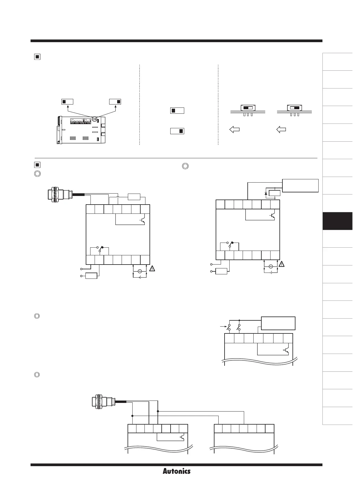
Input logic selection
Input & output connections
● FX Series
Input logic is changeable by input logic
selection switch located at the one-side
of case.
● Please select proper capacity of load, because total
value of load capacity and current consumption should
not be exceed current capacity.(Max. 50mA)
This unit starts to count when "High" level(5-30VDC)
is applied at CP1 or CP2 after selecting PNP.
Please connect as the power of sensor is supplied from only one of counters and design input logic with same way.
●
The capacity of the load must not be exceed max. 30VDC,
max. 100mA of the switching capacity of the transistor.
● Please do not supply the reverse polarity voltage.
※
Please connector the surge absorber(Diode) at both
terminals of the load, in case of using the inductive load.
(Relay, etc.)
Input logic is changeable by
input logic selection switch
located at the terminal block.
Input logic is changeable by input
logic selection switch(SW3) located
at inside of the case.
● FXL Series ● FXH Series
In case of operating the load by power
supply of the sensor
How to count by external power supply
Using 2 counters with one sensor
In case of operating the load by
external power supply
CP1 CP2 +12V 0V
CP1 CP1CP2 CP2+12V +12V0V 0V
Up/Down Counter/Timer
 Loading...