13
924.674.3 - GBINSTRUCTIONS PERTAINING TO THE INSTALLER
17. COnnECtInG tHE MaInS SUpply
Electrical safety of the appliance is only guaranteed by correct grounding, in compliance with the applicable laws and
regulations.
Connect the boiler to a 230V monophase + ground power supply by means of the three-pin cable supplied with it and
make sure you connect polarities correctly.
Use a double-pole switch with a contact separation of at least 3mm in both poles.
In case you replace the power supply cable t a HAR H05 VV-F’ 3x0.75mm
2
cable with an 8mm diameter max.
…access to the power supply terminal block
• isolate the electrical supply to the boiler by the double-pole switch;
• unscrew the two screws securing the control board to the boiler;
• rotate the control board;
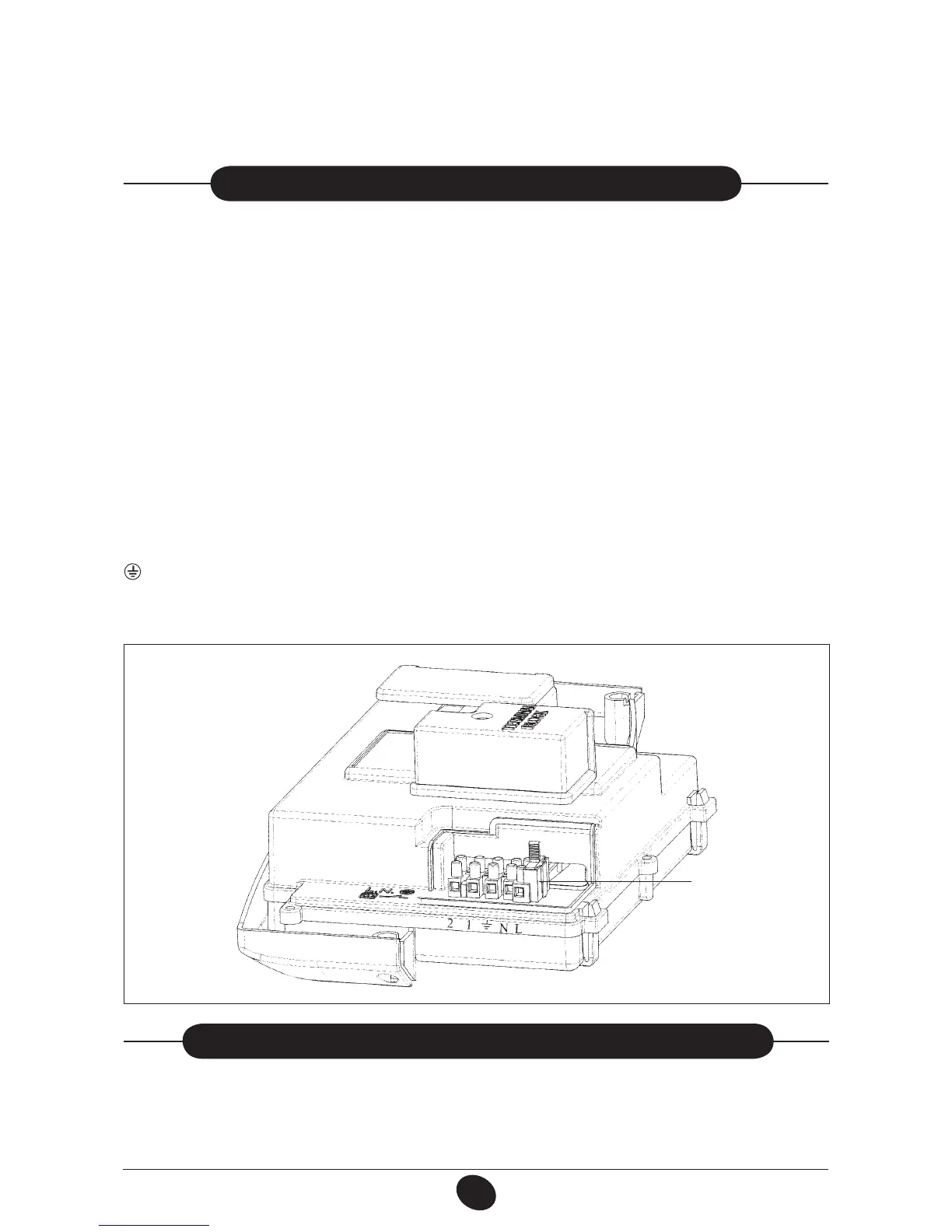
• unscrew the lid and gain access to the wiring (Figure 10).
Important: if tting a single exhaust ue duct, ensure it is adequately insulated (e.g.: with glass wool) wherever the duct
passes through building walls.
For detailed instructions concerning the installation of ttings refer to the technical data accompanying the ttings.
Figure 10
18. fIttInG a ROOM tHERMOStat
• gain access to the power supply terminal block (Figure 10) as described in the previous section;
• remove the jumper placed on terminals (1) and (2);
• insert the duplex cable through the core hitch and connect it to the two terminals.
A 2A fast-blowing fuse is in cor po rated in the power supply terminal block (to check or replace the fuse, pull out the black
fuse carrier).
IMPORTANT: be sure to connect polarities correctly L (LIVE) - N (NEUTRAL).
(L) = Live (brown)
(N) = Neutral (blue)
= Ground (yellow/green)
(1) (2) =
Room thermostat terminals
0607_2301 / CG_1806
TERMINAL BLOCK M1
 Loading...