9
924.674.3 - GBINSTRUCTIONS PERTAINING TO THE INSTALLER
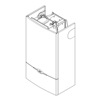
16. INSTALLATION OF FLUE AND AIR DUCTS
Models 240 Fi - 1.240 Fi
We guarantee ease and exibility of instal lation for a gas-
red forced draught boiler thanks to the ttings and xtures
supplied (described below).
The boiler is especially designed for connection to an
exhaust ue / air ducting, with either coaxial, vertical or
horizontal terminal. By means of a splitting kit a two-pipe
system may also be installed.
Exclusively install fittings supplied by the manufac-
turer.
WARNING : To guarantee more operating insurance it
is necessary to assure the flue pipes to the wall using
the apposite clamps.
Figure 7
0503_0905/CG1638
Figure 8
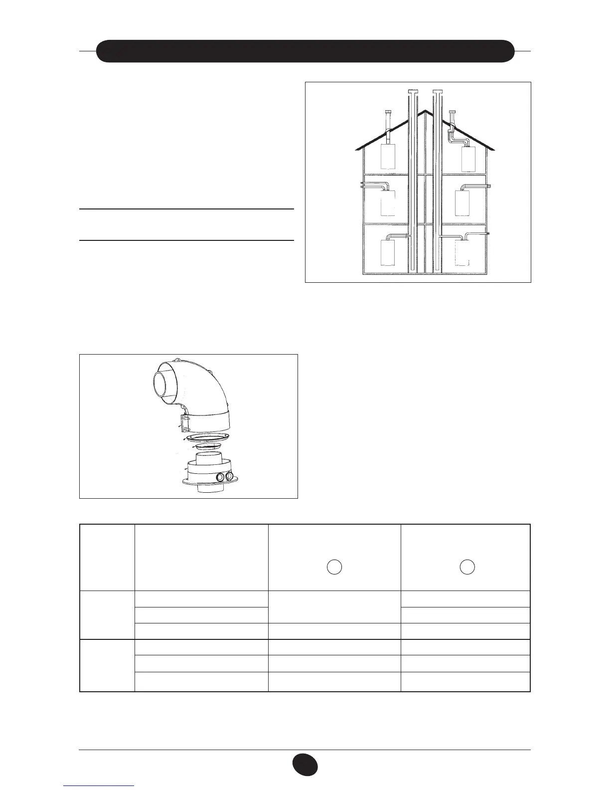
… COAXIAL FLUE - AIR DUCT (CONCENTRIC)
This type of duct allows to disengage exhaust gases and to draw combustion air both outside the building and in case a
LAS ue is tted.
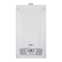
The 90° coaxial bend allows to connect the boiler to a ue-air duct in any direction as it can rotate by 360°. It can moreover
be used as a supplementary bend and be coupled with a coaxial duct or a 45° bend.
0511_2701/CG1750
If the ue outlet is placed outside, the ue-air ducting must
protrude at least 18mm out of the wall to allow alluminium wea-
thering tile to be tted and sealed to avoid water leakages.
Ensure a minimum downward slope of 1 cm towards the
outside per each metre of duct length.
•
A 90° bend reduces the total duct length by 1 metre.
•
A 45° bend reduces the total duct length by 0.5 me-
tre.
The first 90° bend is not included in the maximum avai-
lable length.
Securing clamp
Concentric outlet
A
B
Boiler
model
240 Fi
1.240 Fi
280 Fi
0 ÷ 1
1 ÷ 2
2 ÷ 5
0 ÷ 1
1 ÷ 2
2 ÷ 4
Length (m)
Air suction
RESTRICTOR
B
Yes
No
No
Yes
No
Flue
RESTRICTOR
A
Yes
No
No
Yes
No
No