20
924.674.3 - GBINSTRUCTIONS PERTAINING TO THE INSTALLER
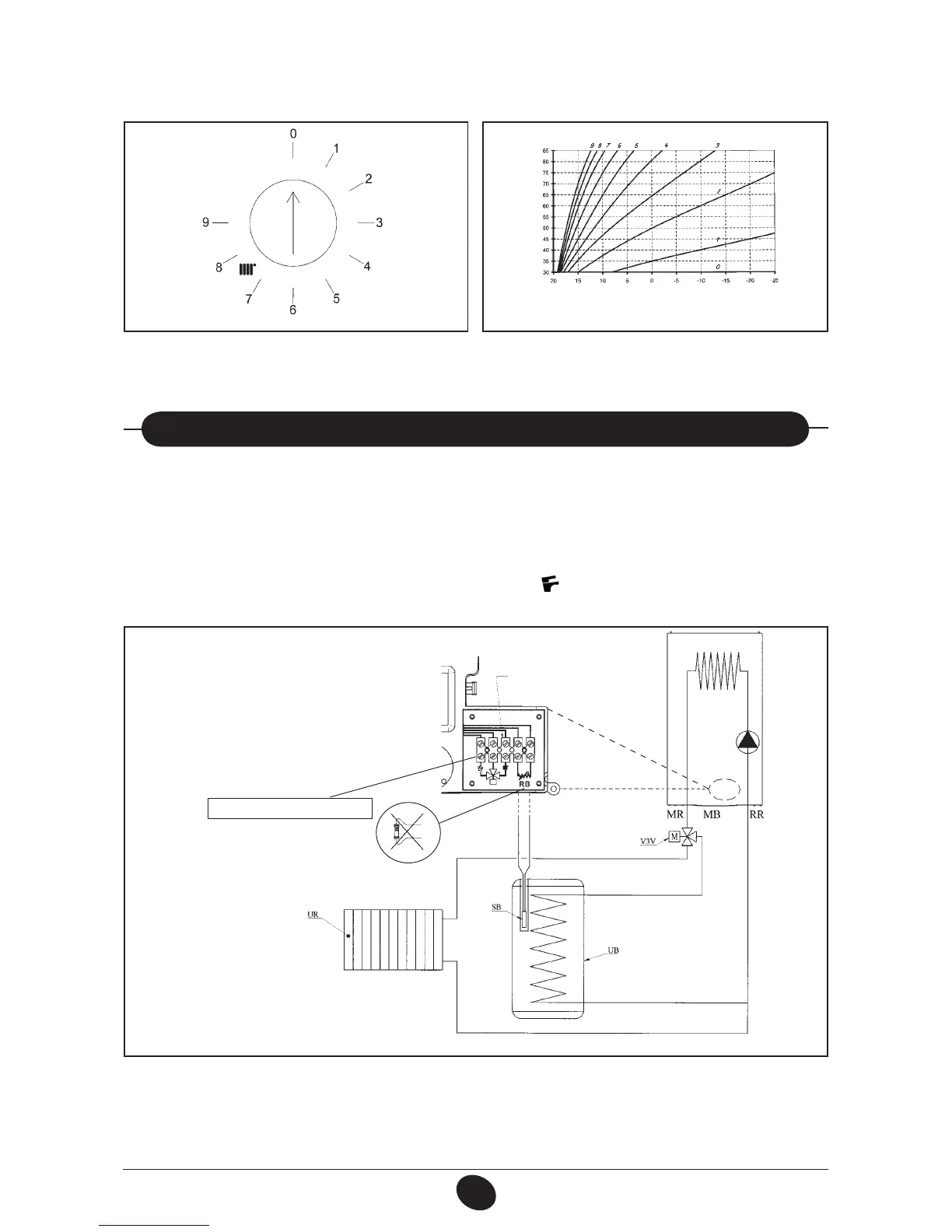
When the external probe is connected, the heating circuit temperature control device (2 - gure 1), regulates the dispersal
coefcient Kt (Figure 18).
The gures below show the relation between knob position and curves. Intermediate curves may also be set.
0503_3102/CG1672
IMPORTANT: the TM delivery temperature value depends on the position of the jumper or the switch T.RISC. (section 23).
The maximum possible temperature setting is 85 or 45°C.
Figure 18
TM = Range delivery temperature
Te = external temperature
0505_3002
TM
Te
For models 1.240 Fi - 1.240 i
IMPORTANT: jumper CN7 must be jumpered (see paragraph 32).
Connect the boiler water pipes as shown in gure 19.
Remove the resistor from terminal board and connect the optional DHW priority sensor to them.
Insert the sensor’s probe in the relevant hole in the boiler.
Set domestic hot water temperature (5°...60 °C) using the control knob
(1 - gure 1).
27. CONNECTING AN EXTERNAL BOILER
Figure 19
0504_1404
Legend
UB DHW boiler unit
UR central heating unit
V3V external three way valve
M2 terminal block
SB DHW priority sensor
MR central heating delivery
MB DHW delivery
RR central heating/DHW return
RB resistor, to be removed
External 3 way valve connection
3 WAY VALVE AND D.K.W. PRIORITY
SENSOR TERMINAL BLOCK.
 Loading...