36 EcoBlue System 7219708 - 01 (04/15)
5 Before Installation
5.5 Unpacking & Initial Preparation
5.5.1 Unpacking
RISK ASSESSMENT - Before commencing the
installation it is recommended that the ‘Five Steps to
Risk Assessment’ document published by the HSE is
consulted, and an assessment performed as described.
GAS SUPPLY - The gas supply, gas type and pressure
must be checked for suitability before connection.
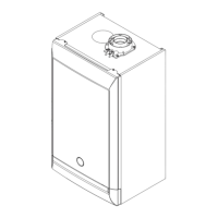
1. See ‘Section 2.3.1 Handling’ before unpacking or lifting the
boiler.
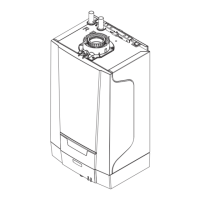
2. Follow the procedure on the carton to unpack the boiler or
see Fig. 14a.
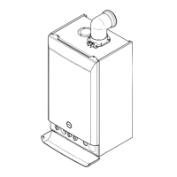
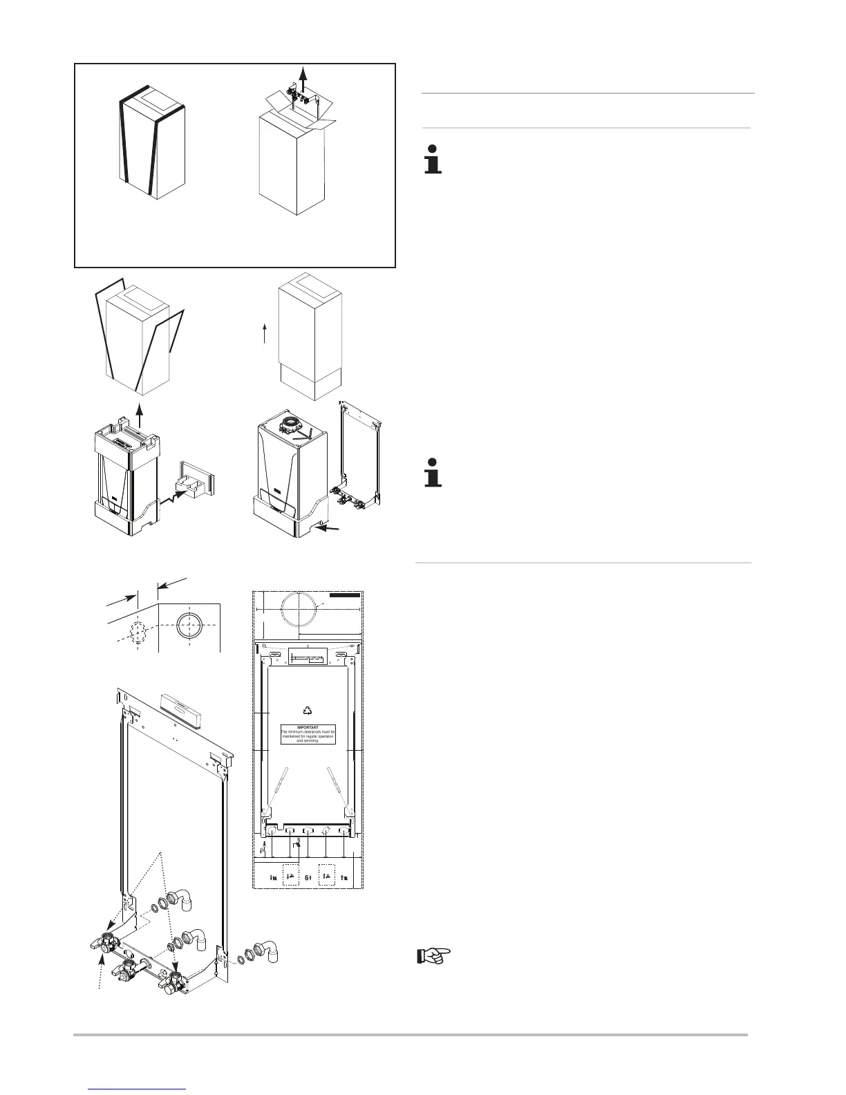
3. If pre-plumbing (Fig. 14) - the wall jig and fitting kit can be
removed without removing the carton sleeve. Simply slide
banding to the edge and open the perforated flap, lift out the jig,
fitting kit and instructions. If the boiler is to be install at a later
date, close the flap and reposition the banding straps, the boiler
can now be store safely away.
A small amount of water may drain from the boiler in the
upright position.
5.5.2 Initial Preparation
1. After considering the location position the fixing template on
the wall ensuring it is level both horizontally and vertically.
2. Mark the position of the fixing slots for the wall jig indicated on
the template.
3. Mark the position of the centre of the flue hole (rear exit). For
side flue exit, mark as shown (Fig. 15).
4. If required, mark the position of the gas and water pipes.
Remove the template (Fig. 17).
5. Cut the hole for the flue (minimum diameter 116mm).
6. Drill the wall as previously marked to accept the wall plugs
supplied. Secure the wall jig using the fixing screws.
7. Using a spirit level ensure that the wall jig is level before
finally tightening the screws (Fig. 16).
8. Connect the gas and water pipes to the valves on the wall jig
using the copper tails supplied. Ensure that the sealing
washers are fitted between the connections.
Fit a suitable filling loop as described in the instructions
supplied with it.
Pressure
Relief
Valve
(15mm)
Condensate
Drain
Part No. 7212143 DRAFT A
5 mm Minimum
Side Clearance
5 mm Minimum
Side Clearance
116mm Dia Minim um
Aperture For Flue Tube
Side Flue
Centre Line
Vertical Flue
Centre Line
175 mm
Minimum
Clearance
Profile of
Outercase
228 mm
150 mm
Minimum
Clearance
Boiler Wall Mounting Plate
Fixing Slots
38.5mm
26.5
mm
65 mm 65 mm 65 mm 65 m m 65 mm
Ø 8 mm
50 mm
162.5mm (PRV)
Hot Water
Outlet
(15mm)
Combi Only
Not System
Cold Water
Inlet
(15mm)
Heating
Return
(22mm)
Heating
Flow
(22mm)
Gas
Inlet
(22mm)
Combi Only
Not System
Part No. 7212143
200 mm
Recommended
Wall Template
130mm
(140mm on 32
model)
For Side Flue Exit
Fig. 15
Fig.16
Heating Flow
3/4” BSP
Connections
Fig. 17
Fig. 14a
SNAP OFF
 Loading...