7219708 - 01 (04/15) EcoBlue System 61
Maintenance 10
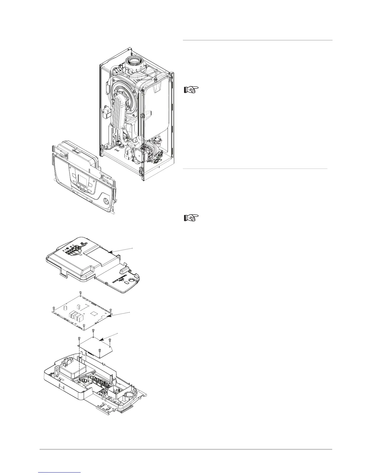
10.3.16 Main P.C.B. (Fig. 64)
1. Ensure that the power to the boiler is isolated.
2. Release the clips securing the control box cover and lift away.
3. Note the position of all plugs and wires on the P.C.B. and
disconnect them.
See Section 3.3 Electrical Diagram for details.
4. Undo the 5 securing screws and remove the P.C.B. It is
retained at the left by two spring latches and the right hand edge
locates in a slot.
5. Reassemble in reverse order, ensuring that the harnesses to
the Control P.C.B. and terminal M2 are routed under the Main
P.C.B. Check the operation of the boiler.
10.3.17 Boiler Control P.C.B. (Fig. 64)
1. Ensure that the power to the boiler is isolated.
2. Release the clips securing the control box cover and lift away.
3. Note the position of all plugs and wires on the P.C.B. and
disconnect them.
See Section 3.3 Electrical Diagram for details.
4. Undo the 5 securing screws and remove the P.C.B. It is
retained at the left by two spring latches and the right hand edge
locates in a slot.
5. Disconnect the link harness between the Main & Control
P.C.B.’s and undo the 4 screws securing the Control P.C.B.
6. Remove the Control P.C.B. and fit the new component.
Reassemble in reverse order, ensuring that the harnesses to the
Control P.C.B. and terminal M2 are routed under the Main P.C.B.
Check the operation of the boiler.
Fig. 67
Control
Box Cover
Main P.C.B.
Boiler Control P.C.B.
 Loading...