91
912.199.3 - GB
ISTRUCTIONS PERTAINING TO THE INSTALLER
12. MAKING THE ELECTRICAL CONNECTIONS
Electrical safety of the appliance is only guaranteed by correct grounding, in accordance with the rules in for-
ce.
Connect the boiler to a 230V monophase + ground power supply by means of the three-pin cable supplied with
it and make sure you connect polarities correctly.
Use a double-pole switch with a contact separation of at least 3mm in both poles.
In case you replace the power supply cable t a HAR H05 VV-F’ 3x0.75mm
2
cable with an 8mm diameter
max.
IMPORTANT: Check that the overall current drawn by accessories connected to the appliance is less
than 2 A. If the value is greater, a relay must be wired between the boiler control circuit board and the
accessories drawing the higher current.
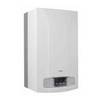
12.1 TERMINAL BLOCKS ACCESS
• Cut off power to the boiler with the two-pole switch.
• Remove the top facia panel cover (which is held by magnets).
• Unscrew the two screws holding the facia panel in place.
• Swing the facia panel forwards.
Main terminal block M1
• Remove the clip-on cover from terminal strip M1.
• The main terminal block incorporates a fast blow 3.15 A fuse (gure 8). Remove the black fuse holder to
check and/or replace the fuse.
Terminal block M2
• Unscrew the xing screw and remove the cover from terminal block M2.
Terminal block M3
• Unscrew the xing screws and remove the main cover.
Figure 8
Terminal board
Terminal board
Cover
Terminal board
Cover
0902_1201 / CT_0674
CAUTION
If the appliance is directly connected to a underoor system, install a safety thermostat to prevent the latter from overheating.

 Loading...