10
4.0 Site Requirements – Page 10
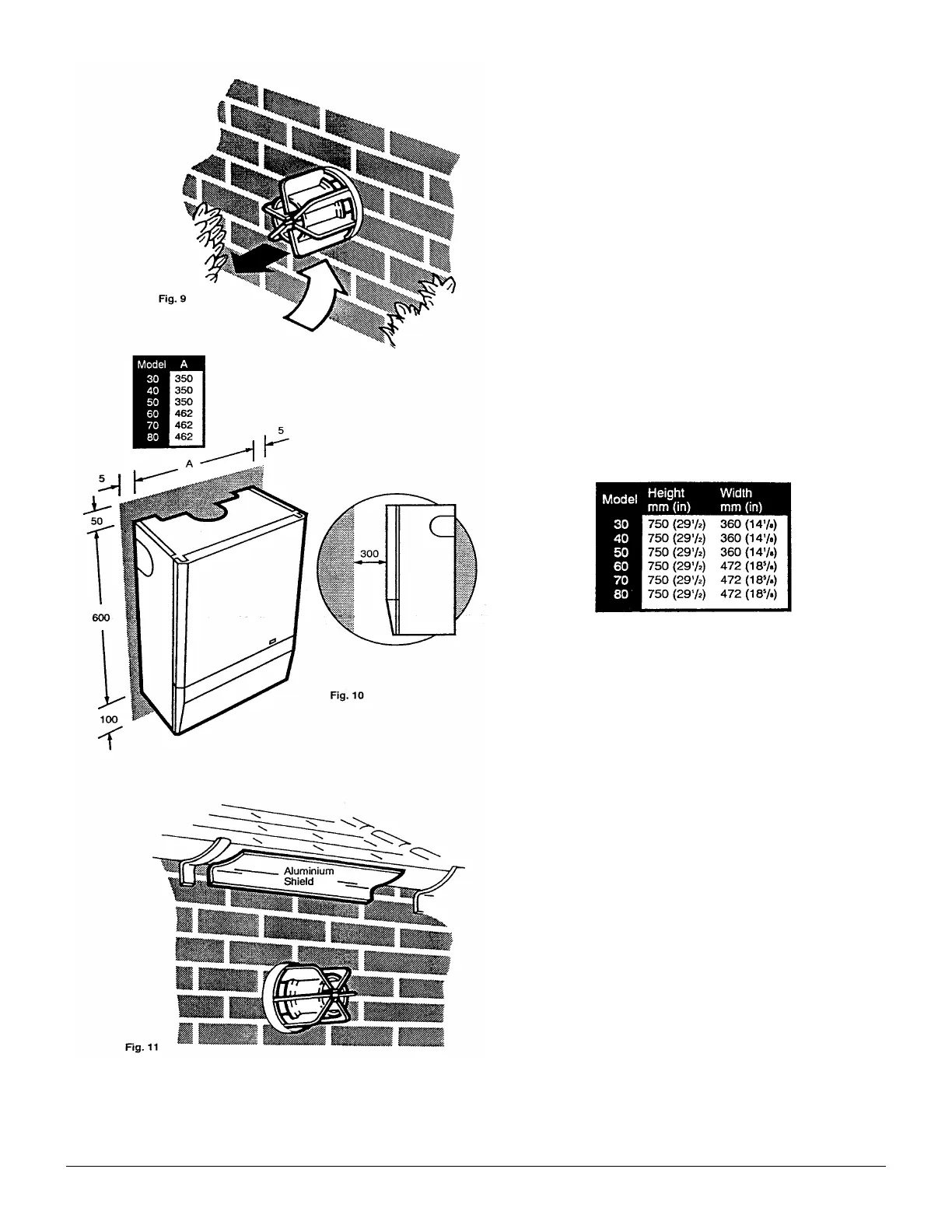
4.1 Location
1. The appliance may be tilted to any suitable wall with
the flue passing through an outside wall and discharging
to atmosphere in a position permitting satisfactory
removal of combustion products and providing an
adequate air supply (Fig. 9). The appliance should be
fitted within the building unless otherwise protected by a
suitable enclosure ie. garage or outhouse. (The appliance
may be fitted inside a cupboard. Cooling ventilation and
insulation of the cupboard are not required,
see section 4.5.)
2. If the appliance is fitted in a room containing a bath or
shower reference must be made to the Current l.E.E.
Wiring Regulations and Building Regulations. If the
appliance is to be fitted into a building of timber frame
construction then reference must be made to British Gas
document DM2.
3. Recommendations for flues are given in BS 5440 Part
1.
4.2 Clearances (Fig. 10)
1. A flat vertical area is required for the installation of the
boiler measuring as shown in the table below for each
model.
2. These dimensions include the necessary clearances
around the appliance for case removal, spanner access
and air movement. Additional clearances may. Be
required for the passage of pipes around local
obstructions such as joists running parallel to the front
face of the appliance.
3. If fitted inside a cupboard the clearance of 300mm
shown is only necessary when the cupboard door is
open. A clearance of 5mm (
3
/
16
in) is required when the
door is dosed.
4.3 Flue Position
1. For installations where the flue terminal is inaccesible
from the outside, an internal fitting kit is available. This
can be obtained free of charge from your local merchant.
2. The following guide lines indicate the general
requirements for siting balanced flue terminals.
3. If the terminal is fitted within 1 metre (39in) of a plastic
gutter, within 500mm (19½ in) of a painted eave or a
painted gutter, an aluminium shield of at least 1 metre
(39in) long should be fitted to the underside of the gutter
or painted surface. An air space of 5mm (
3
/
16
in) should
be left between shield and gutter (Fig. 11).
4. If the terminal discharges onto a pathway or
passageway, check that combustion products will not
cause a nuisance and that the terminal will not obstruct
the passageway.
5. If the outer surface of an outside wail is of combustible
material, it should be protected by fitting the flue trim
provided.
 Loading...