Electrical installation
Synchronous servomotor 21Version: 2.1
8 Electrical installation
8.1 Important notes
DANGER
Serious risk of injury through electric shock!
• Only staffs qualified and trained in electrical engineering are allowed to wire up the Motor.
Check the assignment of the servo terminal and the motor.Compare the rated voltage and the rated cur-
rent of the devices.
• Always make sure that the motors are de-energised during assembly and wiring, i.e. no voltage may be
switched on for any piece of equipment which is to be connected. Ensure that the control cabinet re-
mains turned off (barrier, warning signs etc.). The individual voltages will only be turned on again during
commissioning.
• Never undo the electrical connections to the motor when it is live.
• Control and power leads may be live, even if the motor is not running.
NOTE
Failure free operation
• Ensure that the servo terminal and the motor are earthed properly.See below for further information re-
garding EMC shielding and earthing.Earth the mounting plate and motor housing.
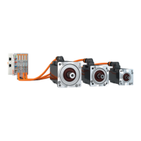
• Only use cables approved by Beckhoff for operating the AM8100 with the “one-cable technology” (OCT).
• Route the power and control cables as separately as possible from one another (separation > 20
cm).This will improve the immunity of the system to electromagnetic interference.If a motor power cable
is used which includes integral brake control leads, then these brake control leads must be shielded.The
shielding must be connected at both ends (see sectionShielding concept)
• Install all cables carrying a heavy current with an adequate cross-section, as per EN 60204. The recom-
mended cross-section can be found in the technical data.
• Wiring
ð Connect the feedback cable
ð Connect the motor cables
ð Connect shields to shield terminals or EMC connectors at both ends
ð Connect the motor holding brake
NOTE
HF interference
The ground symbol , which you will find in the wiring diagrams, indicates that you must provide an
electrical connection, with as large a surface area as possible, between the unit indicated and the mounting
plate in the control cabinet.This connection is to suppress HF interference and must not be confused with
the PE (protective earth) symbol (protective measure according to EN 60204).
 Loading...