Error handling and diagnostics
5 Error handling and diagnostics
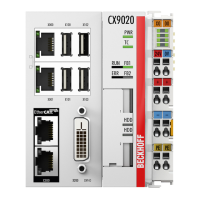
5.1 Basic CPU module
5.1.1 LEDs on the basic CPU module
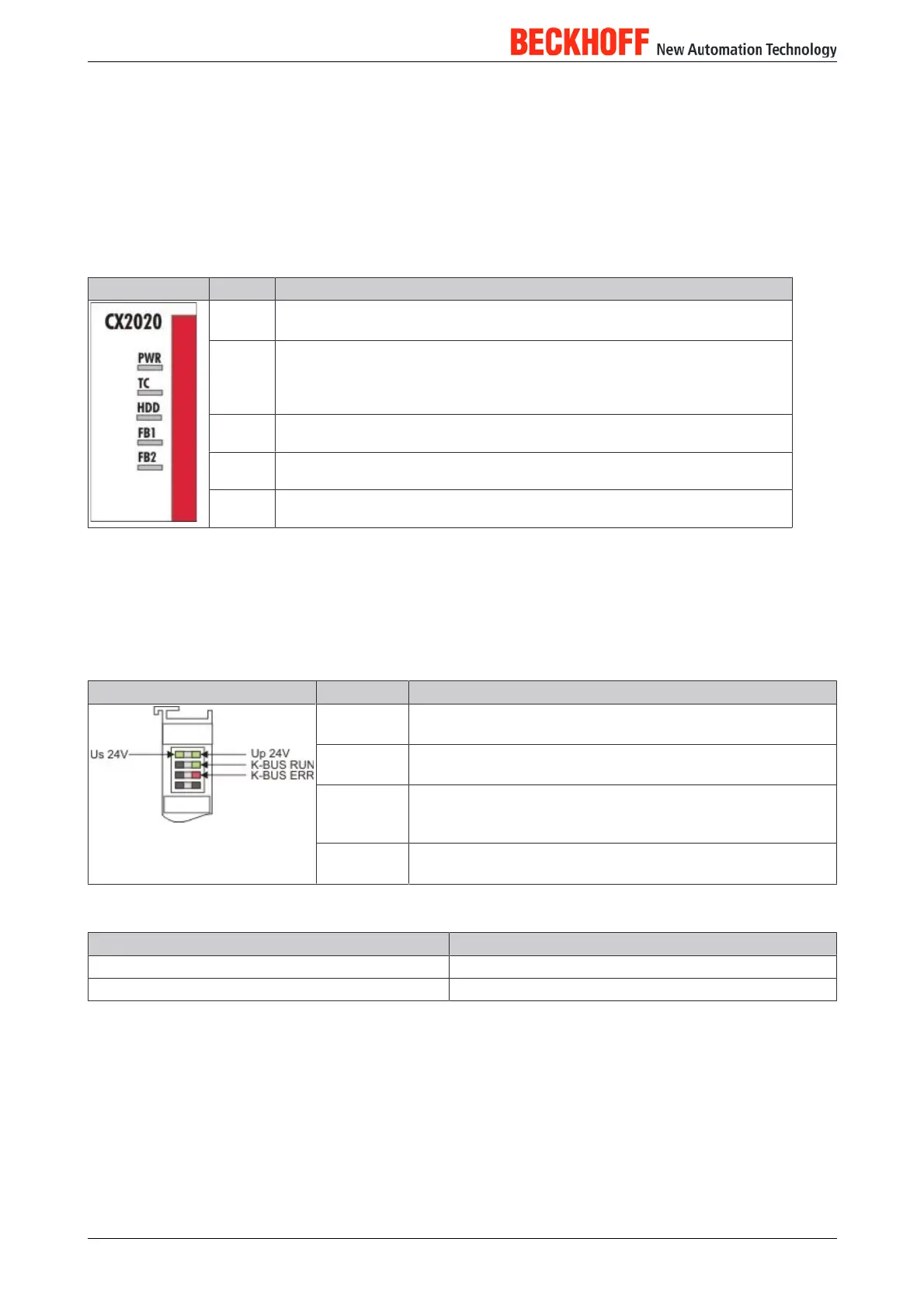
Display LED Meaning
PWR Power supply The Power LED comes on when the device is connected to
a live power supply unit (green).
TC TwinCAT status LED TwinCAT is in Run mode (green)
TwinCAT is in Stop mode (red)
TwinCAT is in Config mode (blue)
HDD Read/Write Compact Flash (red) Indicates access to the CFast card.
FB1 Status LED1 for fieldbus (function is written at the fieldbus interface)
FB2 Status LED2 for fieldbus (function is written at the fieldbus interface)
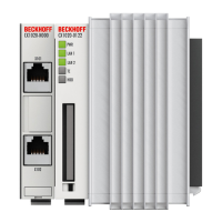
5.1.2 LEDs of the power supply (CX21000004) in KBus mode
After switching on, the power supply immediately checks the connected Bus Terminal configuration. If KBus
terminals are detected, the errorfree bootup is signalled by the red “I/O ERR LED” going out. If the ”I/O
ERR" LED blinks, an error in the area of the terminals is indicated. The error code can be determined from
the frequency and number of blinks. This permits rapid rectification of the error.
Display LED Meaning
Us 24 V Power supply for the CPU module The LED lights green if the
power supply is correct.
Up 24V Power supply for terminal bus. The LED lights green if the
power supply is correct.
KBUS RUN KBus diagnostics The green LED lights up in order to indi
cate faultfree operation. "Faultfree" means that the commu
nication with the fieldbus system is also running.
KBUS ERR KBus diagnostics The red LED flashes to indicate an error.
The red LED blinks with two different frequencies.
Table 10: The I/O error LED blink code
fast blinking Start of the error code
first slow sequence Error code
second slow sequence Error code argument
CX2020, CX2030, CX204038
Version 1.2
 Loading...