Mounting and wiring
EK110x, EK15xx38 Version: 3.6
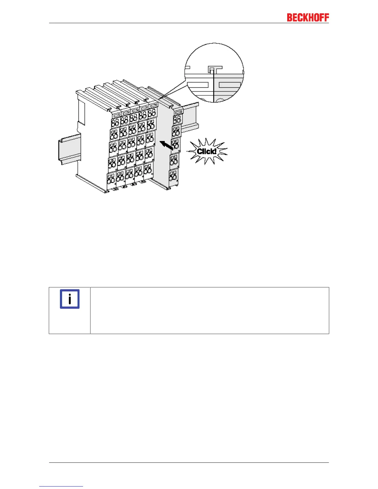
Assembly
Fig.22: Attaching on mounting rail
The Bus Coupler and Bus Terminals are attached to commercially available 35mm mounting rails (DIN rails
according to EN60715) by applying slight pressure:
1. First attach the Fieldbus Coupler to the mounting rail.
2. The Bus Terminals are now attached on the right-hand side of the Fieldbus Coupler. Join the compo-
nents with tongue and groove and push the terminals against the mounting rail, until the lock clicks
onto the mounting rail.
If the Terminals are clipped onto the mounting rail first and then pushed together without tongue and
groove, the connection will not be operational! When correctly assembled, no significant gap should
be visible between the housings.
Note
Fixing of mounting rails
The locking mechanism of the terminals and couplers extends to the profile of the mounting
rail. At the installation, the locking mechanism of the components must not come into con-
flict with the fixing bolts of the mounting rail. To mount the mounting rails with a height of
7.5mm under the terminals and couplers, you should use flat mounting connections (e.g.
countersunk screws or blind rivets).
 Loading...