Product overview
EL10xx, EL11xx 31Version: 4.5
2.6 EL1124, EL1144, EL1134 - Introduction
Four-channel digital input terminals + 5 / 12 / 48V
DC
The EL1124 (5V
DC
), EL1144 (12V
DC
) and EL1134 (48V
DC
) digital input terminals acquire the binary control
signals and transmit them, in an electrically isolated form, to the higher-level automation unit. The EtherCAT
Terminals contain four channels that indicate their signal state by means of light emitting diodes. These
versions have different input voltages.
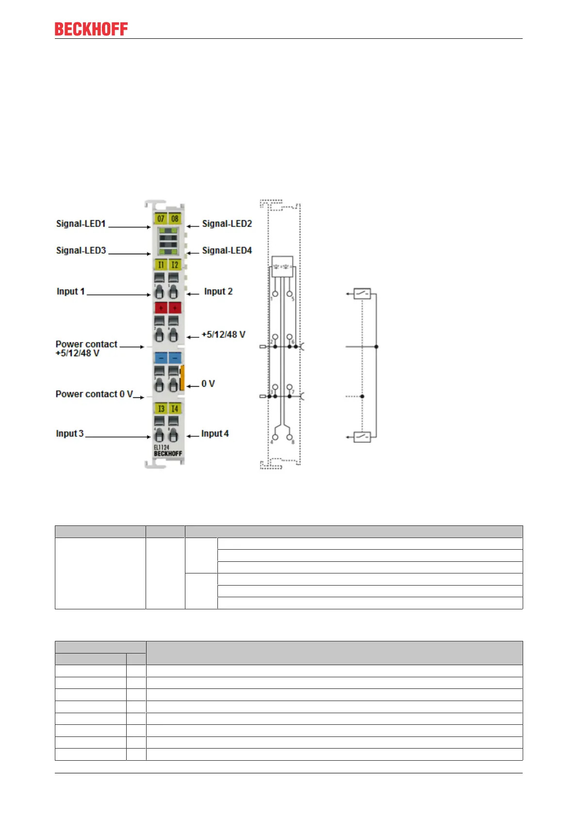
2.6.1 EL1124, EL1144, EL1134 - LEDs and connection
Fig.21: EL1124
EL1124, EL1144, EL1134 - LEDs
LED Color Meaning
INPUT 1- 4 green off EL1124: Signal voltage "0" (< 0.8V)
EL1144: Signal voltage "0" (< 2,4V)
EL1134: Signal voltage "0" (-3…5V)
on EL1124: Signal voltage "1" (> 2.4V)
EL1144: Signal voltage "1" (> 8.5V)
EL1134: Signal voltage "1" (15…30V)
EL1124, EL1144, EL1134 - Connection
Terminal point Description
Name No.
Input 1 1 Input 1
+ 5 / 12 / 48V 2 + 5 / 12 / 48V (internally connected to terminal point 6 and positive power contact)
0V 3 0V (internally connected to terminal point7 and negative power contact)
Input 3 4 Input 3
Input 2 5 Input 2
+ 5 / 12 / 48V 6 + 5 / 12 / 48V (internally connected to terminal point 2 and positive power contact)
0V 7 0V (internally connected to terminal point3 and negative power contact)
Input 4 8 Input 4

 Loading...