Operation
EL290434 Version: 3.2.2
5.2.5 TwinSAFE reaction times
The TwinSAFE terminals form a modular safety system that exchanges safety-oriented data via the Safety-
over-EtherCAT protocol. This chapter is intended to help you determine the system's reaction time from the
change of signal at the sensor to the reaction at the actuator.
Typical response time
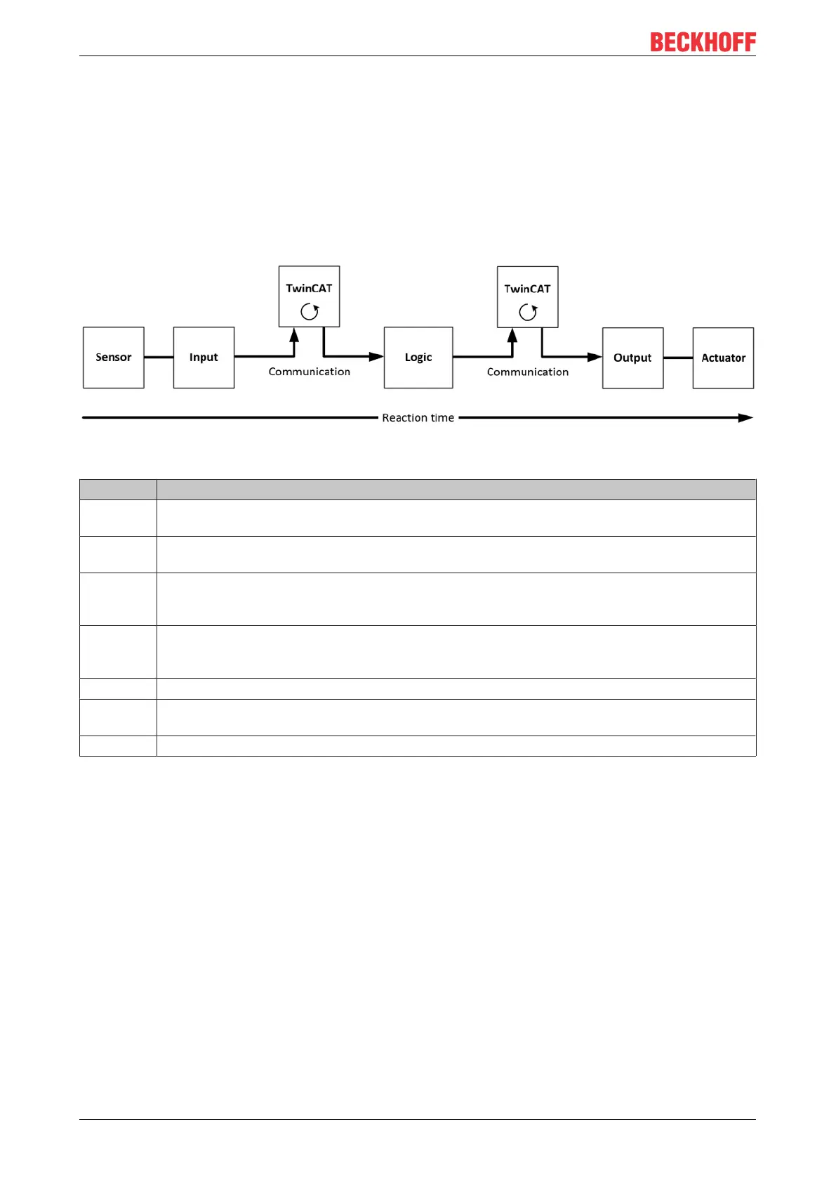
The typical response time is the time required for transferring a piece of information from the sensor to the
actuator, when the whole system operates normally, without error.
Fig.15: Typical response time
Definition Description
RT
Sensor
Response time of the sensor, until the signal is made available at the interface. Typically
provided by the sensor manufacturer.
RT
Input
Response time of the safe input, e.g. EL1904 or EP1908. This time can be found in the
technical data. In the case of the EL1904 it is 4ms.
RT
Comm
Response time of the communication. This is typically 3 times the EtherCAT cycle time, since a
new Safety-over-EtherCAT telegram has to be generated before new data can be sent. These
times depend directly on the higher-level standard controller (cycle time of the PLC/NC).
RT
Logic
Response time of the logic terminal. This is the cycle time of the logic terminal and typically
ranges from 500µs to 10ms for the EL6900, depending on the size of the safety project. The
actual cycle time can be read from the terminal.
RT
Output
Response time of the output terminal. This is typically between 2 and 3ms.
RT
Actuator
Response time of the actuator. This information is typically provided by the actuator
manufacturer
WD
Comm
Watchdog time of the communication
The typical response time is based on the following formula:
3 * 3 *
typ Sensor Input Comm Logic Comm Output Actuator
ReactionTime RT RT RT RT RT RT RT= + + + + + +
with
5 4 3*1 10 3*1 3 20 48
typ
ReactionTime ms ms ms ms ms ms ms ms= + + + + + + =
Worst case response time
The worst-case response time is the maximum time required for switching off the actuator in the event of an
error.

 Loading...


