54 55Quick Start Guide
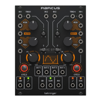
ABACUS
(PL) Maksymalne czasy funkcji – kanał 1 i kanał 4
Pokrętła oraz Attenuverter ustawione na maksimum (całkowicie w prawo)
Czas
narastania
Szczyt
narastania
Czas
opadania
Minimum
opadania
Czas cyklu
Log 9 m 0 s 9.48 v 25 m 15 s 0.03 v 42 m 45 s
Lin 55 s 9.48 v 50 s 0.03 v 1 m 45 s
Exp 7 s 4.5 v 5 s 0.03 v 10 s
Podpowiedzi i sugestie
• Kanały 1 i 4 mogą być używane do wzajemnej modulacji funkcji
Rise (narastanie), Fall (opadanie) lub Both (obydwa).
• Sygnał trigger EOC (końca cyklu) kanału 4 może być użyty do wzbudzenia
zewnętrznego generatora Sample & Hold, który może być następnie użyty
jako źródło modulacji.
• Wyjście EOR (końca narastania) kanału 1 może być użyte jako modykator
dowolnego wejścia CV na kanałach 1 i 4, lub jako wejście zewnętrznego
napięcia na dowolnym kanale.
• Kanały 2 i 3 mogą być użyte w celu dostarczenia napięcia równoważącego
dla wejść CV kanałów 1 i 4.
• Eksperymentuj z odwróconą sumą napięć jako źródła kontroli.
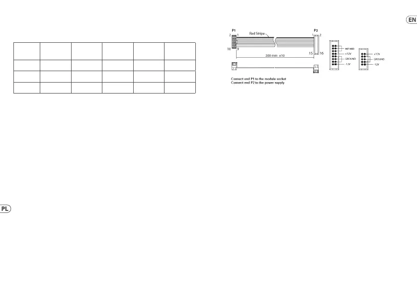
(EN) Power Connection
The module comes with the required power cable for connecting to a standard
Eurorack power supply system. Follow these steps to connect power to the
module. It is easier to make these connections before the module has been
mounted into a rack case.
1. Turn the power supply or rack case power o and disconnect the
power cable.
2. Insert the 16-pin connector on the power cable into the socket on the
power supply or rack case. The connector has a tab that will align with the
gap in the socket, so it cannot be inserted incorrectly. If the power supply
does not have a keyed socket, be sure to orient pin 1 (-12 V) with the red
stripe on the cable.
3. Insert the 10-pin connector into the socket on the back of the module. The
connector has a tab that will align with the socket for correct orientation.
4. After both ends of the power cable have been securely attached, you may
mount the module in a case and turn on the power supply.
Installation
The necessary screws are included with the module for mounting in a
Eurorack case. Connect the power cable before mounting.
Depending on the rack case, there may be a series of xed holes spaced 2 HP apart
along the length of the case, or a track that allows individual threaded plates to
 Loading...