English
9
Setting cams and mechanical stops (AQ7L)
AQ7L has both mechanical stops and cams that can be set.
Setting travel limits
The mechanical stops limit
the actuator travel.
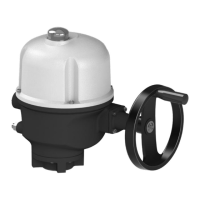
Fine adjustment of the stop
screws position is possible
within a limit of ±2°
maximum. These screws are
located in the lower section
of the actuator.
The actuator stops on open
or closed position when the
travel limit switch is
tripped.
How to adjust cams and mechanical stops for both directions
actuator output.
1. Untighten the nut corresponding to clockwise mechanical
stop and turn stop screw 2 turns back.
2. Drive the actuator to clockwise travel limit position.
3. Get the clockwise stop screw in contact with output sleeve
then turn it back of 1.5 turns.
4. Retighten nut to keep position of mechanical stop.
5. Set the cam corresponding to clockwise travel limit switch.
If the clockwise signalling switch is wired:
6. Drive the output slightly in the counter-clockwise direction
using manual override.
7. Set the cam corresponding to clockwise signalling switch.
8. Untighten the nut corresponding to counter-clockwise
mechanical stop and turn stop screw 2 turns back.
9. Drive the actuator to the counter-clockwise travel limit
position.
10. Redo settings steps 3 to 7 for counter-clockwise direction.
 Loading...